


39 (EN)
TRIGGER
PLUG IN POWER
CONTROL S
IN OUT
REMOTE
RS-422A
INDEX
ABL LINK
IN OUT
VIDEO
S VIDEO
Y IN
C IN
INPUT A
R-Y/PR
R
Y
G
B-Y/PB
B SYNC/HD VD
OUT
IN
IN OUT
MODE
REMOTE1
OUT
IN
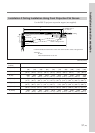
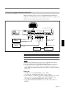
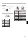
Choose the appropriate cable from the following table.
1 m 2 m 5 m 10 m 15 m 25 m 50 m
— CCQ-2BRS CCQ-5BRS CCQ-10BRS — CCQ-25BRS CCQ-50BRS
SIC-M-1 — SIC-M-5 — SIC-M-15 SIC-M-25 SIC-M-50
Notes
• Insert the female and male plugs of the SIC-M or CCQ-BRS cable correctly.
• You can extend the SIC-M or CCQ-BRS cable up to 50 m.
• The video signal input to the signal interface board installed to the INPUT B
section should not exceed 70 MHz. When projecting the video signal which
exceeds 70 MHz, connect the signal source to the INPUT A connectors using the
5BNC cables.
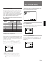
Setting up
• Set INPUT-A in the SET SETTING menu to RGB.
For details, see “The SET SETTING Menu” on page 31 (EN).
• Select VIDEO or S VIDEO by pressing the INPUT SELECT keys on the
remote control or by setting VIDEO in the INPUT SELECT menu.
For details, see “The INPUT SELECT Menu” on page 25 (EN).
• Set the SINGLE/SECOND/OTHER select switch on the switcher to
SINGLE.
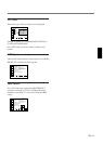
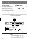
Rear
IFB-40 Signal Interface Board
IN
VIDEO IN
to video output
SIC-M or CCQ-BRS
connecting cable
Video
equipment
to RGB output
to S video output
PC-1271/1271M
Switcher
Video
equipment
to REMOTE 1 OUT
Computer
Using the Signal Interface Switcher
When you connect the PC-1271/1271M Signal Interface Switcher (not
supplied) to the IFB-40 Signal Interface Board (installed on the projector by
default), you can connect easily various input sources.
S VIDEO IN
R
G
B
VD
SYNC/HD