9
Location of Controls
a Ventilation holes (intake)/Air
filter cover
b Adjusters (fore pad)
c Lamp cover
d Adjuster
Adjusts the picture position. (1 page
23)
e S VIDEO INPUT connector (mini
DIN 4-pin)
Connects to the S video output of video
equipment.
f VIDEO INPUT connector (phono
type)
Connects to the video output of video
equipment.
g INPUT A connector (HD D-sub
15-pin, female)
Inputs a computer signal, video GBR
signal, component signal, or DTV signal
depending on the connected equipment.
Connects to the output connector of
equipment using the supplied cable or an
optional cable.
h Rear remote control detector
i HDMI connector
Connects to the video output connector
of the video equipment or the computer
equipped with HDMI/DVI output
connector (digital).
j SERVICE RS-232C connector
(D-sub 9-pin, female)
Used for service only.
This is not for customers’ use.
k AC IN socket
Connects the supplied AC power cord.
l Adjuster adjustment button
Press to pull out the adjuster. (1 page
23)
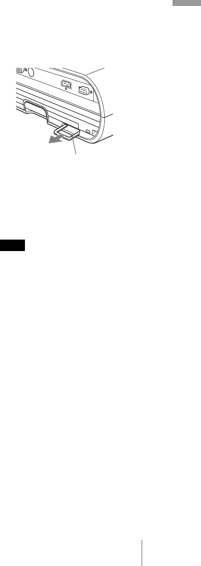
m Security bar
An anti-theft chain or wire
(commercially available) can be
connected to this bar.
If it is difficult to pull out, pull out the
security bar using a screwdriver.
qf Security lock
Connects to an optional security cable
(from Kensington).
Web page address:
http://www.kensington.com/
To maintain optimal performance, clean the
air filter whenever you replace the lamp. (1
page 51)
Note
Security bar


