


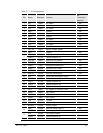
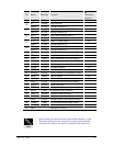

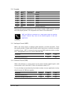
LZT 123 1834 31
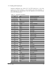
Pin Name Direction Function
PIN
Connection
Required
35 TX_ON Output Transmit indication
RI Output Ring Indicator
36
GPIO8 In/Out General purpose IO
DTR1 Input Data Terminal Ready (UART1) Yes
2
37
GPIO10 In/Out General purpose IO
DCD1 Output Data Carrier Detect (UART1)
38
GPIO11 In/Out General purpose IO
RTS1 Input Ready To Send (UART1) Yes
2
39
GPIO9 In/Out General purpose IO
CTS1 Output Clear To Send (UART1) Yes
2
40
GPIO12 In/Out General purpose IO
41 DTM1 Input Data To Module from host (UART1) Yes
3
42 DFM1 Output Data From Module to host (UART1) Yes
3
43 DTM3 Input Data To Module from host (UART3)
44 DFM3 Output Data From Module to host (UART3)
45 USBDP In/Out USB data positive Yes
4
46 USBDN In/Out USB data negative Yes
4
47 SSPDTM Input Serial PCM data to module from host
48 SSPDFM Output Serial PCM data from module to host
49 VUSB Input USB DC power Yes
4
50 ALARM Output RTC alarm
51 SSPFS In/Out Serial PCM frame synchronization
52 SSPCLK In/Out Serial PCM clock
53 MICIP Input Microphone input positive
54 MICIN Input Microphone input negative
55 EARP Output Earpiece output positive
56 EARN Output Earpiece output negative
57 AUXO Output Auxiliary audio from module to host
58 SERVICE Input Flash programming enable signal
59 AUXI Input Auxiliary audio to module from host
60 AREF - Analogue reference
1
- These signals are required if the external SIM interface is used
2
- These pin connections are required for sleep mode operation
3, 4
- At least one of these interfaces is required to be connected
NOTE