


LZT 123 1834 73
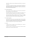
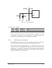
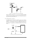
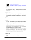
Figure 5.20-2 Typical host-side circuit for ALARM output
VRTC is specified to work down to 1.1V across the environmental operating
conditions of the GR64. Integrators may discover in controlled environments that the
VRTC interface will function reliably as low as 0.8V, so best practice would be to
design the circuitry to operate down to 0.7V.
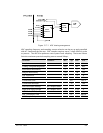
5.20.3 ALARM Utilization as a Wake-up
The ALARM output can be used by the host application to wake up from standby or
hibernation mode, but it can also be used to completely power up the host
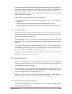
application. The example below shows how the ALARM output (marked
Out
on
Figure 5.20-2, and
In
on Figure 5.20-3) triggers the enabling of the main power to
the application. The application has a parallel hold transistor (V4), and a Start
Button.
Figure 5.20-3 Example of host wake-up circuit