


LZT 123 1834 54
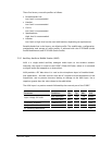
PCMCLK (bit clock) and PCMSYNC (frame synchronization) are both generated by the
DSP within the wireless modem. The DSP within the wireless modem in this instance
is the master for all external PCM, so clocks and data from external devices must be
synchronized to it.
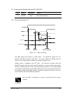
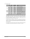
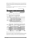
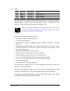
For standard GSM voice a 13-Bit PCM data word is embedded in a 16-bit word frame,
as shown in Figure 5.10-1 below.
LSBMSB
D0
D15
13-bit sample occupies these frame bits
sample LSB justified
LSBMSB
D0
D15
13-bit sample occupies these frame bits
sample LSB justified
Figure 5.10-1 Typical 16-bit PCM Voice Sample Word Format
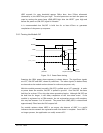
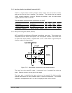
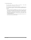
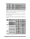
Typical PCM data transfer is shown in the following figures.
MSB
MSB
LSB
LSB
SSPCLK
SSPFS
SSPDFM
SSPDTM
Q
Q
MSB
MSB
LSB
LSB
SSPCLK
SSPFS
SSPDFM
SSPDTM
Q
Q
Figure 5.10-2 PCM Frame format for a single transfer
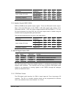
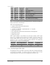
MSB
MSB
LSB
LSB
LSB
LSB
MSB
MSB
Frame nFrame n-1 Frame n+1
SSPCLK
SSPFS
SSPDFM
SSPDTM
MSB
MSB
LSB
LSB
LSB
LSB
MSB
MSB
Frame nFrame n-1 Frame n+1
SSPCLK
SSPFS
SSPDFM
SSPDTM
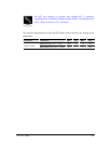
Figure 5.10-3 PCM Frame format for a continuous transfer
The PCM interface has a Slave mode, however the allocated DSP buffer size limits the
maximum data rate available. A separate Application Note describing slave mode
implementation can be obtained from Sony Ericsson through Customer Support.