


LZT 123 1834 63
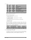
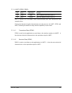
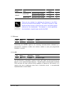
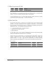
Signal Mode Value
Minimum input voltage 2.5 V
Active High
Maximum input voltage 12.0 V
SERVICE
Inactive Low Maximum input voltage 0.8 V
There are two methods for updating the firmware in the GR64:
Sony Ericsson Emma III and Updater. The Emma III system is a web
based tool that accesses a Sony Ericsson server from which signed
software can be downloaded. The Updater is a local application
that downloads a signed image provided by SEMC.
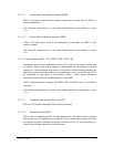
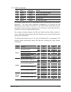
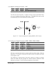
5.13 Buzzer
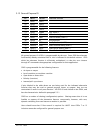
Pin Name Direction Function
31 BUZZER Output Buzzer Output
Connecting the BUZZER signal to an inverting transistor-buffer followed by a
piezoelectric transducer enables the wireless modem to play pre-programmed
melodies or sounds.
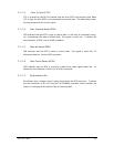
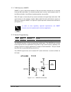
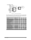
5.14 LED
Pin Name Direction Function
33 LED Output LED control signal
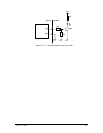
The LED interface is intended to operate a status LED, which can be programmed on
and off, or for a particular blink sequence. The LED signal is derived from a standard
GPIO and does not have sufficient drive capability to operate an LED directly, so it
requires the user to implement some form of transistor circuit. A recommended
implementation is shown below.
NOTE