


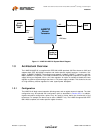
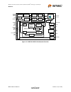

MII/RMII 10/100 Ethernet Transceiver with HP Auto-MDIX and flexPWR
®
Technology in a Small Footprint
Datasheet
Revision 1.0 (04-15-09) 14 SMSC LAN8710/LAN8710i
DATASHEET
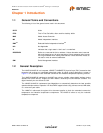
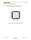
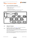
Chapter 3 Pin Description
This chapter describes the signals on each pin. When a lower case “n” is used at the beginning of the
signal name, it indicates that the signal is active low. For example, nRST indicates that the reset signal
is active low. The buffer type for each signal is indicated in the TYPE column, and a description of the
buffer types is provided in Table 3.1.
Note 3.1 Unless otherwise noted in the pin description, internal pull-up and pull-down resistors are
always enabled. The internal pull-up and pull-down resistors prevent unconnected inputs
from floating, and must not be relied upon to drive signals external to
LAN8710/LAN8710i.
When connected to a load that must be pulled high or low, an external resistor must be
added.
Note: The digital signals are not 5V tolerant.They are variable voltage from +1.6V to +3.6V, as shown
in Table 7.1.
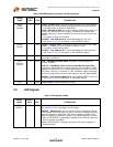
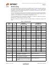
3.1 MAC Interface Signals
Table 3.1 Buffer Types
BUFFER TYPE DESCRIPTION
I8 Input.
O8 Output with 8mA sink and 8mA source.
IOD8 Input/Open-drain output with 8mA sink.
IPU
Note 3.1
Input with 67k (typical) internal pull-up.
IPD
Note 3.1
Input with 67k (typical) internal pull-down.
IOPU
Note 3.1
Input/Output with 67k (typical) internal pull-up. Output has 8mA sink and 8mA source.
IOPD
Note 3.1
Input/Output with 67k (typical) internal pull-down. Output has 8mA sink and 8mA source.
AI Analog input
AIO Analog bi-directional
ICLK Crystal oscillator input pin
OCLK Crystal oscillator output pin
P Power pin
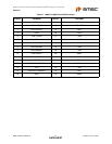
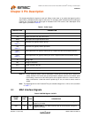
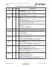
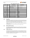
Table 3.2 MII/RMII Signals 32-QFN
SIGNAL
NAME
32-QFN
PIN # TYPE DESCRIPTION
TXD0 22 I8 Transmit Data 0: The MAC transmits data to the transceiver using this
signal in all modes.
TXD1 23 I8 Transmit Data 1: The MAC transmits data to the transceiver using this
signal in all modes