


Hi-Speed USB 2.0 to 10/100 Ethernet Controller
Datasheet
SMSC LAN9500/LAN9500i 11 Revision 1.7 (10-02-08)
DATASHEET
1
Transmit Data
3
(External
PHY Mode)
TXD3 O8
(PU)
Transmit Data 3: In external PHY mode, this pin
functions as the transmit data 3 output to the
external PHY.
General
Purpose I/O 7
(Internal PHY
Mode Only)
GPIO7 IS/O8/
OD8
(PU)
General Purpose I/O 7
EEPROM
Size
Configuration
Strap
EEP_SIZE IS
(PU)
EEPROM SIZE: The EEP_SIZE strap selects the
size of the EEPROM attached to the
LAN9500/LAN9500i.
0 = 128 byte EEPROM is attached and a total of
seven address bits are used.
1 = 256/512 byte EEPROM is attached and a
total of nine address bits are used.
Note: A 3-wire style 1K/2K/4K EEPROM that
is organized for 128 x 8-bit or 256/512 x
8-bit operation must be used.
See Note 2.1 for more information on
configuration straps.
1
Transmit Data
2
(External
PHY Mode)
TXD2 O8
(PD)
Transmit Data 2: In external PHY mode, this pin
functions as the transmit data 2 output to the
external PHY.
General
Purpose I/O 6
(Internal PHY
Mode Only)
GPIO6 IS/O8/
OD8
(PU)
General Purpose I/O 6
USB Port
Swap
Configuration
Strap
PORT_SWAP
IS
(PD)
USB Port Swap Configuration Strap: Swaps
the mapping of USBDP and USBDM.
0 = USBDP maps to the USB D+ line and
USBDM maps to the USB D- line.
1 = USBDP maps to the USB D- line. USBDM
maps to the USB D+ line.
See Note 2.1 for more information on
configuration straps.
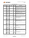
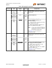
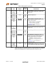
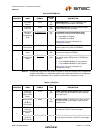
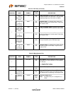
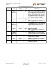
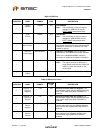
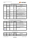
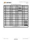
Table 2.1 MII Interface Pins (continued)
NUM PINS NAME SYMBOL
BUFFER
TYPE DESCRIPTION