


Hi-Speed USB 2.0 to 10/100 Ethernet Controller
Datasheet
Revision 1.7 (10-02-08) 40 SMSC LAN9500/LAN9500i
DATASHEET
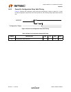
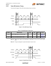
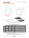
Chapter 5 Package Outline
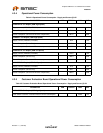
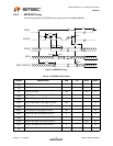
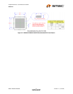
Notes:
1. All dimensions are in millimeters unless otherwise noted.
2. Position tolerance of each terminal and exposed pad is +/- 0.05 mm at maximum material condition. Dimension
“b” applies to plated terminals and is measured between 0.15 and 0.30 mm from the terminal tip.
3. The pin 1 identifier may vary, but is always located within the zone indicated.
Figure 5.1 LAN9500/LAN9500i 56-QFN Package
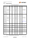
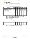
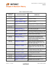
Table 5.1 LAN9500/LAN9500i 56-QFN Dimensions
MIN NOMINAL MAX REMARKS
A 0.70 - 1.00 Overall Package Height
A1 0.00 0.02 0.05 Standoff
A2 - - 0.90 Mold Cap Thickness
D/E 7.85 8.00 8.15 X/Y Body Size
D1/E1 7.55 - 7.95 X/Y Mold Cap Size
D2/E2 5.75 5.90 6.05 X/Y Exposed Pad Size
L 0.30 - 0.50 Terminal Length
b 0.18 0.25 0.30 Terminal Width
e 0.50 BSC Terminal Pitch