


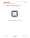
Small Footprint RMII 10/100 Ethernet Transceiver with HP Auto-MDIX Support
Datasheet
Revision 1.0 (05-28-09) 16 SMSC LAN8720/LAN8720i
DATASHEET
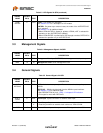
3.3 Management Signals
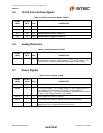
3.4 General Signals
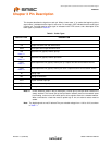
LED2/
nINTSEL
2IOPULED2 – Link speed LED Indication.
See Section 5.3.7 for a description of LED modes.
nINTSEL: On power-up or external reset, the mode of the nINT/REFCLKO
pin is selected.
See Section 4.10 for additional detail.
When LED2/nINTSEL is floated or pulled to VDD2A, nINT is selected for
operation on pin nINT/REFCLKO (default).
When LED2/nINTSEL is pulled low to VSS through a resistor, REFCLKO is
selected for operation on pin nINT/REFCLKO.
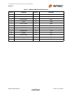
Table 3.4 Management Signals 24-QFN
SIGNAL
NAME
24-QFN
PIN # TYPE DESCRIPTION
MDIO 12 IOD8 Management Data Input/OUTPUT: Serial management data input/output.
MDC 13 I8 Management Clock: Serial management clock.
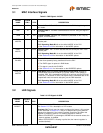
Table 3.5 General Signals 24-QFN
SIGNAL
NAME
24-QFN
PIN # TYPE DESCRIPTION
nINT/
REFCLKO
14 IOPU nINT – Active low interrupt output. Place an external resistor pull-up to
VDDIO.
REFCLKO – 50MHz clock derived from the 25MHz crystal oscillator.
See Section 4.7.2 for additional detail.
See DESCRIPTION of pin 2: LED2 – Link speed LED Indication.
This signal is mux’d with REFCLKO.
XTAL1/
CLKIN
5ICLKClock Input: Crystal connection or external clock input.
XTAL2 4 OCL
K
Clock Output: Crystal connection.
Float this pin when an external clock is driven to XTAL1/CLKIN.
nRST 15 IOPU External Reset: Input of the system reset. This signal is active LOW.
Table 3.3 LED Signals 24-QFN (continued)
SIGNAL
NAME
24-QFN
PIN # TYPE DESCRIPTION