


Small Footprint RMII 10/100 Ethernet Transceiver with HP Auto-MDIX Support
Datasheet
Revision 1.0 (05-28-09) 54 SMSC LAN8720/LAN8720i
DATASHEET
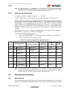
The MODE[2:0] hardware configuration pins are multiplexed with other signals as shown in Table 5.40.
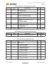
Table 5.39 MODE[2:0] Bus
MODE[2:0] MODE DEFINITIONS
DEFAULT REGISTER BIT VALUES
REGISTER 0 REGISTER 4
[13,12,10,8] [8,7,6,5]
000 10Base-T Half Duplex. Auto-negotiation disabled. 0000 N/A
001 10Base-T Full Duplex. Auto-negotiation disabled. 0001 N/A
010 100Base-TX Half Duplex. Auto-negotiation
disabled.
CRS is active during Transmit & Receive.
1000 N/A
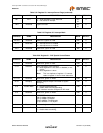
011 100Base-TX Full Duplex. Auto-negotiation disabled.
CRS is active during Receive.
1001 N/A
100 100Base-TX Half Duplex is advertised. Auto-
negotiation enabled.
CRS is active during Transmit & Receive.
1100 0100
101 Repeater mode. Auto-negotiation enabled.
100Base-TX Half Duplex is advertised.
CRS is active during Receive.
1100 0100
110 Power Down mode. In this mode the transceiver will
wake-up in Power-Down mode. The transceiver
cannot be used when the MODE[2:0] bits are set to
this mode. To exit this mode, the MODE bits in
Register 18.7:5(see Table 5.30) must be configured
to some other value and a soft reset must be
issued.
N/A N/A
111 All capable. Auto-negotiation enabled. X10X 1111
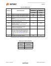
Table 5.40 Pin Names for Mode Bits
MODE BIT PIN NAME
MODE[0] RXD0/MODE0
MODE[1] RXD1/MODE1
MODE[2] CRS_DV/MODE2