Ultra Fast USB 2.0 Multi-Format Flash Media Controller/USB Hub Combo
SMSC USB2640/USB2641 17 Revision 2.0 (10-03-08)
DATASHEET
Chapter 6 Pin Descriptions
This section provides a detailed description of each signal. The signals are arranged in functional
groups according to their associated interface.
The “n” symbol in the signal name indicates that the active, or asserted, state occurs when the signal
is at a low voltage level. When “n” is not present before the signal name, the signal is asserted when
at the high voltage level.
The terms assertion and negation are used exclusively. This is done to avoid confusion when working
with a mixture of “active low” and “active high” signal. The term assert, or assertion, indicates that a
signal is active, independent of whether that level is represented by a high or low voltage. The term
negate, or negation, indicates that a signal is inactive.
6.1 USB2640/USB2641 Pin Descriptions
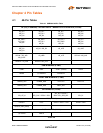
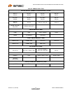
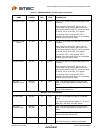
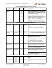
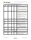
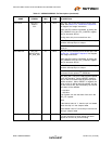
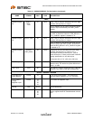
Table 6.1 USB2640/USB2641 Pin Descriptions
NAME SYMBOL
48-PIN
QFN
BUFFER
TYPE DESCRIPTION
xD INTERFACE (APPLIES ONLY TO USB2640)
xD Write Protect xD_nWP 21 O12PD This pin is an active low write protect signal for the
xD device.
This pin has a weak pull-down resistor that is
permanently enabled.
xD Address
Strobe
xD_ALE 23 O12PD This pin is an active high Address Latch Enable
signal for the xD device.
This pin has a weak pull-down resistor that is
permanently enabled.
xD Command
Strobe
xD_CLE 24 O12PD This pin is an active high Command Latch Enable
signal for the xD device.
This pin has a weak pull-down resistor that is
permanently enabled.
xD Data 7-0 xD_D[7:0] 30
32
33
13
17
18
19
20
I/O12PD These pins are the bi-directional data signal
xD_D7 - xD_D0.
The bi-directional data signal has an internal weak
pull-down resistor.
xD Read Enable xD_nRE 27 O12PU This pin is an active low read strobe signal for the
xD device.
When using the internal FET, this pin has an
internal weak pull-up resistor that is tied to the
output of the internal Power FET and is controlled
by the xD_PU bit of the xDC_CTL register.
If an external FET is used (Internal FET is
disabled), then the internal pull-up is not available
(external pull-ups must be used).


