


Ultra Fast USB 2.0 Multi-Format Flash Media Controller/USB Hub Combo
Revision 2.0 (10-03-08) 48 SMSC USB2640/USB2641
DATASHEET
7.3.4.1 Implementation Characteristics
The device will only access an EEPROM using the Sequential Read Protocol.
7.3.4.2 Pull-Up Resistor
The circuit board designer is required to place external pull-up resistors (10 kΩ recommended) on the
SDA/SMBDATA & SCL/SMBCLK/CFG_SELO lines (per SMBus 1.0 Specification, and EEPROM
manufacturer guidelines) to Vcc in order to assure proper operation.
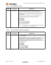
7.3.5 In-Circuit EEPROM Programming
The EEPROM can be programmed via ATE by pulling RESET_N low (which tri-states the device’s
EEPROM interface and allows an external source to program the EEPROM).
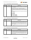
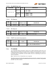
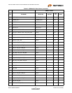
7.4 Default Configuration Option:
The SMSC device can be configured via its internal default configuration. Please see Section 7.3.2,
"EEPROM Data Descriptor" for specific details on how to enable default configuration.
Please refer to Table 7.1 for the internal default values that are loaded when this option is selected.
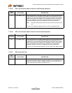
7.5 Reset
There are two different resets that the device experiences. One is a hardware reset (either from the
internal POR reset circuit or via the RESET_N pin) and the second is a USB Bus Reset.
7.5.1 Internal POR Hardware Reset
All reset timing parameters are guaranteed by design.
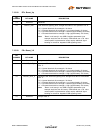
7.5.2 External Hardware RESET_N
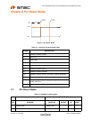
A valid hardware reset is defined as assertion of RESET_N for a minimum of 1 μs after all power
supplies are within operating range. While reset is asserted, the device (and its associated external
circuitry) consumes less than 500 μA of current from the upstream USB power source.
Assertion of RESET_N (external pin) causes the following:
1. All downstream ports are disabled, and PRTCTL power to downstream devices is removed.
2. The PHYs are disabled, and the differential pairs will be in a high-impedance state.
3. All transactions immediately terminate; no states are saved.
4. All internal registers return to the default state (in most cases, 00h).
5. The external crystal oscillator is halted.
6. The PLL is halted.