


Ultra Fast USB 2.0 Multi-Format Flash Media Controller/USB Hub Combo
SMSC USB2640/USB2641 49 Revision 2.0 (10-03-08)
DATASHEET
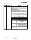
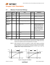
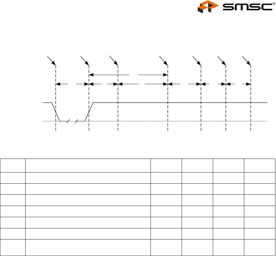
7.5.2.1 RESET_N for EEPROM Configuration
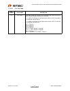
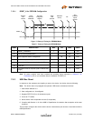
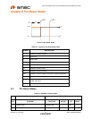
Figure 7.1 Reset_N Timing for EEPROM Mode
Note: All power supplies must have reached the operating levels mandated in Chapter 9, DC
Parameters, prior to (or coincident with) the assertion of RESET_N.
7.5.3 USB Bus Reset
In response to the upstream port signaling a reset to the device, the device does the following:
Note: The device does not propagate the upstream USB reset to downstream devices.
1. Sets default address to 0.
2. Sets configuration to: Unconfigured.
3. Negates PRTCTL[3:2] to all downstream ports.
4. Clears all TT buffers.
5. Moves device from suspended to active (if suspended).
6. Complies with Section 11.10 of the USB 2.0 Specification for behavior after completion of the reset
sequence.
The host then configures the device and the device’s downstream port devices in accordance with the
USB Specification.
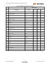
Table 7.7 Reset_N Timing for EEPROM Mode
NAME DESCRIPTION MIN TYP MAX UNITS
t1 RESET_N asserted. 1 μsec
t2 Device recovery/stabilization. 500 μsec
t3 8051 programs device configuration 20 50 msec
t4 USB attach (See Note). 100 msec
t5 Host acknowledges attach and signals USB reset. 100 msec
t6 USB idle. Undefined msec
t7 Completion time for requests (with or without data
stage).
5 msec
t1
t2
t4
t5
t6 t7
RESET_N
VSS
Hardware
reset
asserted
Device
Recovery/
Stabilization
8051 Sets
Configuration
Registers
Attach
USB
Upstream
USB Reset
recovery
Idle
Start
completion
request
response
t3