


Ultra Fast USB 2.0 Multi-Format Flash Media Controller/USB Hub Combo
SMSC USB2640/USB2641 33 Revision 2.0 (10-03-08)
DATASHEET
7.3.2.10 A4h-A5h: LUN Power Configuration
The USB2640/USB2641 has one internal FET which can be utilized for card power. The settings are
stored in NVSTORE and provide the following features:
1.A card can be powered by an external FET or internal FET.
2.The power limit can be set to 100 mA (Default) or 200 mA for the internal FET.
Each media uses two bytes to store its LUN power configuration. Bit 3 selects between internal or
external. For internal FETs Bits 0 through 2 are used for the power limit. Only 2 of the possible 8 values
are currently specified.
7.3.2.11 A8h: LED Blink Interval (1 byte)
7.3.2.12 A9h: Blink Duration (1 byte)
7.3.3 LUN ID Strings
There are four LUN ID strings corresponding to LUN# 0, 1, 2, and 3: Number of Icons to Display, SM
LUN #, MS LUN #, SD/MMC LUN #. The SM value will be overridden with xD once an xD-Picture Card
has been identified.
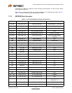
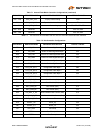
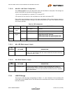
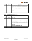
Table 7.4 FET Configuration
FET TYPE BITS BIT TYPE DESCRIPTION
0FET Low
Byte
3:0 Low Nibble Unused.
1 7:4 High Nibble Unused.
2FET High
Byte
3:0 Low Nibble 0000b Disabled.
0001b External FET Enabled.
1000b Internal FET with 100 mA power limit.
1010b Internal FET with 200 mA power limit.
3 7:4 High Nibble Unused.
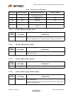
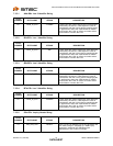
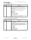
BIT
NUMBER BIT NAME DESCRIPTION
7:0 LED_BLK_INT The blink rate is programmable in 10 ms intervals. Hi bit indicates idle state:
0-Off, 1-On. The remaining bits are used to determine the blink interval up
to a max of 128 x 10 ms.
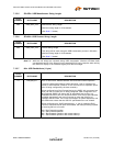
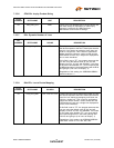
BIT
NUMBER BIT NAME DESCRIPTION
7:0 LED_BLK_DUR LED blink After Access. This byte is used to designate the number of
seconds that the GPIO 0 LED will continue to blink after a drive access.
Setting this byte to "05" will cause the GPIO 0 LED to blink for 5 seconds
after a drive access.