


Ultra Fast USB 2.0 Multi-Format Flash Media Controller/USB Hub Combo
SMSC USB2640/USB2641 47 Revision 2.0 (10-03-08)
DATASHEET
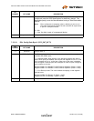
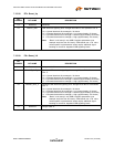
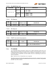
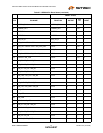
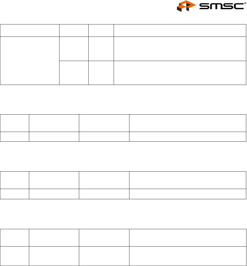
7.3.3.33 F4h: MS/SD Clock Limit
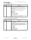
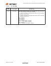
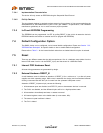
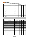
7.3.3.34 F5h: Reserved
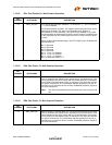
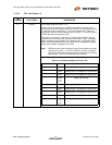
7.3.3.35 F6h: Reserved
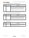
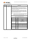
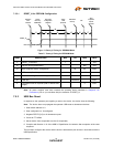
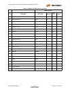
7.3.3.36 FCh-FFh:
Non-volatile Storage Signature
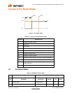
7.3.4 I
2
C EEPROM
The I
2
C EEPROM interface implements a subset of the I
2
C Master Specification (Please refer to the
Philips Semiconductor Standard I
2
C-Bus Specification for details on I
2
C bus protocols). The device’s
I
2
C EEPROM interface is designed to attach to a single “dedicated” I
2
C EEPROM, and it conforms to
the Standard-mode I
2
C Specification (100 kbit/s transfer rate and 7-bit addressing) for protocol and
electrical compatibility.
Note: Extensions to the I
2
C Specification are not supported.
The device acts as the master and generates the serial clock SCL, controls the bus access
(determines which device acts as the transmitter and which device acts as the receiver), and generates
the START and STOP conditions.
BYTE NAME TYPE BITS DESCRIPTION
MS_SD_CLK_LIM
Upper
Nibble Bits
7:4 0: MS - 60 MHz -- Default, no limit
1: MS - 40 MHz
2: MS - 20 MHz
3: MS - 15 MHz
Lower
Nibble Bits
3:0 0: SD/MMC - 48 MHz
1: SD/MMC - 24 MHz
2: SD/MMC - 20 MHz
3: SD/MMC - 15 MHz
BIT
NUMBER BYTE NAME DEFAULT VALUE DESCRIPTION
7:0 Reserved 66h Reserved.
BIT
NUMBER BYTE NAME DEFAULT VALUE DESCRIPTION
7:0 Reserved 00h Reserved for media usage.
BYTE
NUMBER BYTE NAME STRING DESCRIPTION
7:0 NVSTORE_SIG “ATA2” This signature is used to verify the validity of the
data in the configuration area. The signature must be
set to ‘ATA2’ for USB2640/USB2641.