


52
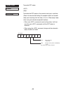
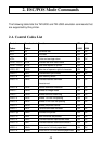
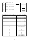
Table 3-1 Header 1 (First Byte)
Bit Content Status 0 Status 1
0 Always 1
1
2 Printer Status Byte Count
3
4 Always 0
5 Printer Status Byte Count
6 Reserved (Fixed at 0)
7 Not Used (Fixed at 0)
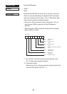
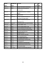
Table 3-2 Relationship of Actual Transmitted Byte Count and Header 1
Transmitted Byte Count n (7 n 15) Header 1
7 00001111B (0F Hex)
8 00100001B (21 Hex)
9 00100011B (23 Hex)
10 00100101B (25 Hex)
11 00100111B (27 Hex)
12 00101001B (29 Hex)
13 00101011B (2B Hex)
14 00101101B (2D Hex)
15 00101111B (2F Hex)
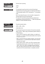
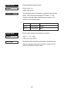
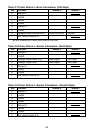
Header 2
Header 2 is the information of the length of one byte transmitted in the second
byte of the automatic status. Table 3-3 shows the composition of the Header
2. Header 2 shows the version of the automatic status with bits 1 to 3 and bit
5 (called automatic status version below). For reference, Table 3-3 shows the
relationship between the actual version and the Header 2.
The automatic status version will be upgraded when new information is added
to the currently empty printer status bit positions through the addition of new
functions in the future. When the host does not manage the automatic status
version, it is acceptable that Header 2 be ignored.