PARTS REPLACEMENT
4-3
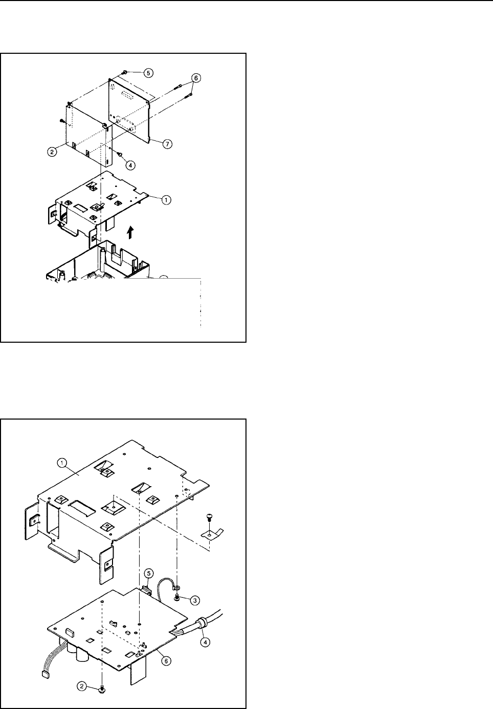
4.3 Main Logic Board
1. Turn off the power switch, disconnect the power cord
from wall outlet.
2. Remove
• Printer Mechanism according to the procedure
described in Section 4.2
3. Main Chassis 1 and Board Chassis 2 from Lower
Case 3.
4. Remove
• Cable unit and connector
• Two screws(Main chassis) 4
• Two screws(Board) 5
• Two screws and spacers(interface connector) 6
• Main logic board 7
4.4 Power Supply Unit
1. Remove
• Main chassis 1 according to the procedure de-
scribed in Section 4.3.
• One screw with wire 3
• Two screws 2 for transformer
• Remove the power supply cord 4, the power
switch 5 and the power supply unit 6 by sliding
it.


