PARTS REPLACEMENT
4-7
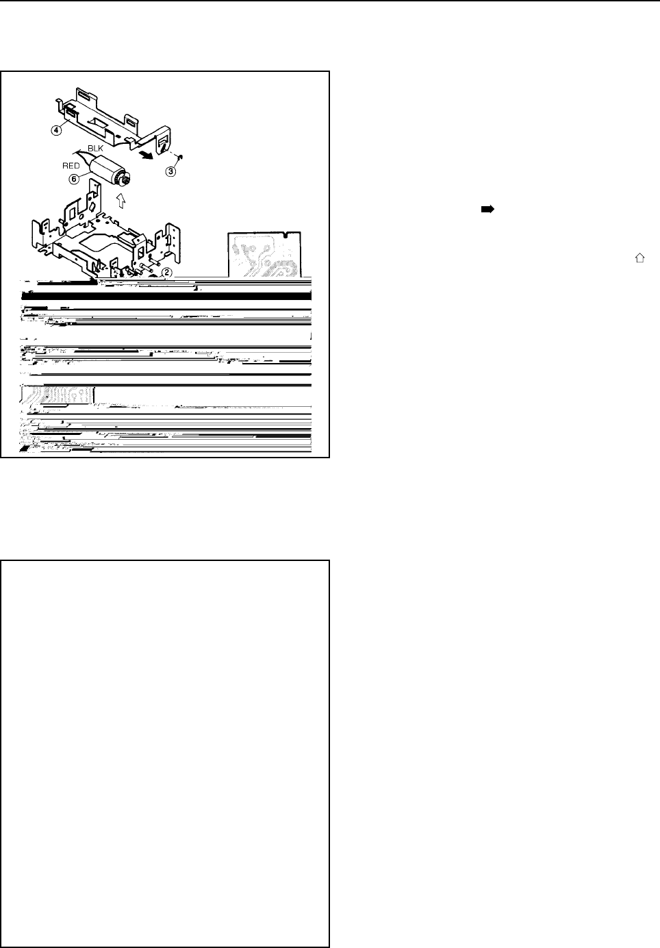
1. Removal
• Remove the printer mechanism according to the
procedure of item 4.2.
• Two solderd lead wires (Black and red)
• Stop ring 1
• Gear 2
• Stop ring 3
• Slide the ribbon base (W) 4 in the direction of
the black arrow and remove it.
• Screw 5
• Secure the frame and forcibly open the carriage
motor unit in the direction of the white arrow .
• Carriage motor unit 6
2. Adjustment
• After assembling, adjust the cam position of the
ribbon color change mechanism by referring to
item 3.4.
• After that, adjust the column slippage by refer-
ring to item 3.3.
4.11 Paper End Switch Board Unit
1. Remove
• Printer mechanism according to the procedure des-
cribed in Section 4.2.
• The two soldered lead wires 1 with the soldering
iron. (White)
• Screw 2
• Paper end switch board unit 3
<SP216/246>


