PARTS REPLACEMENT
4-6
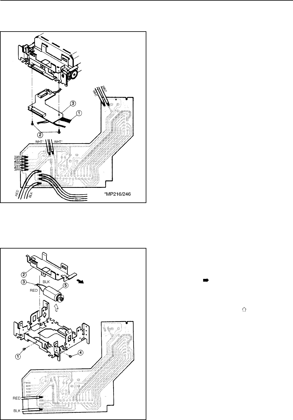
4.9 Thermal Board Unit
1. Remove
• Printer mechanism according to the procedure des-
cribed in Section4.2.
• The eleven soldered lead wires 1 with the sol-
dering iron.(MP212/242)
• The thirteen soldered lead wires 1 with the sol-
dering iron.(MP216/246)
• Two screws 2
• Thermal board unit 3
4.10 Carriage Motor Unit
1. Remove
• Printer mechanism according to procedure de-
scribed in Section 4.2.
• Screw 1 and the ribbon base 2 after sliding
blackarrow direction.
• The two soldered lead wires 3 with the soldering
iron. (black,red)
• Screw 4
• Lift the unit to white arrow direction after
wildering the frame.
• Carriage motor unit 5 .
2. Adjustment
After assembling,adjust the column displacement accord-
ing to the procedure described in 3.3.
<SP212/242>


