


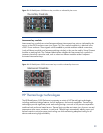

4x DDR single-port mezzanine card will work equally well in
Mezzanine 1, Mezzanine 2, or Mezzanine 3 connectors.
Both types of mezzanine cards use a 450-pin connector, enabling up to eight lanes of differential
transmit and receive signals—in other words, up to two x1 connections, up to two x4 connections, or
a single x8 connection.
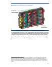
Because the connections between the device bays and the interconnect bays are hard-wired through
the signal midplane, the mezzanine cards must be matched to the appropriate type of interconnect
module. For example, a Fibre Channel mezzanine card must be placed in the mezzanine connector
that connects to an interconnect bay holding a Fibre Channel switch. To simplify installing various
mezzanine cards and interconnect modules, the Onboard Administrator uses an electronic keying
process to detect any mismatch between the mezzanine cards and the interconnect modules. The most
up-to-date information about c-Class mezzanine card options is available at
http://h18004.www1.hp.com/products/blades/components/c-class-interconnects.html.
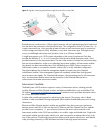
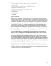
Virtual Connect
With c-Class architecture, HP introduced a new type of interconnect technology: Virtual Connect. As it
is implemented in the c-Class architecture, Virtual Connect technology provides virtualized server I/O
connections to the Ethernet (LAN) or Fibre Channel (SAN) networks. Virtual Connect technology
virtualizes the server-edge so that networks can communicate with pools of HP BladeSystem servers
rather than in a conventional one-to-one relationship. HP recommends using Virtual Connect or
managed switches to reduce cabling and management overhead.
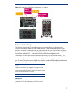
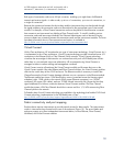
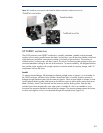
Virtual Connect consists of hardware (the Virtual Connect module) and firmware that runs on the
Virtual Connect module. Like other Ethernet and Fibre Channel switches, the Virtual Connect modules
slide into the switch bays of the c3000 enclosure. The Ethernet module is necessary to install Fibre
Channel because the Virtual Connect Manager software runs on a processor on the Ethernet module.
The Ethernet module has sixteen 1-GbE downlinks to servers (connected across the Nonstop signal
midplane), eight 1-GbE uplinks to the network (RJ45 copper Ethernet connectors), two 10-GbE
connectors (for copper CX4 cables), and one 10-GbE internal inter-switch link (across the NonStop
signal midplane) for a failover connection between Virtual Connect modules. The Fibre Channel
module has sixteen 4-Gb Fibre Channel downlinks to servers and four 1/2/4-Gb auto-sensing Fibre
Channel uplinks to the network.
Full details about Virtual Connect technology are available in the technology brief entitled “HP Virtual
Connect technology implementation for the HP BladeSystem c-Class”:
http://h20000.www2.hp.com/bc/docs/support/SupportManual/c00814156/c00814156.pdf.
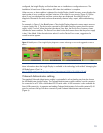
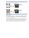
Fabric connectivity and port mapping
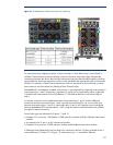
Each enclosure requires interconnects to provide network access for data transfer. The interconnects
reside in interconnect bays located on the rear of the enclosure (Figure 10). The server blades and
enclosure support up to three independent interconnect fabrics, such as Ethernet, Fibre Channel,
InfiniBand, and Virtual Connect modules.
18