


DE100i-A100 User's Guide - Rev. C02 StorCase Technology, Inc.
Installation 7
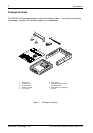
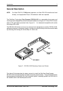
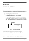
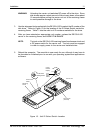
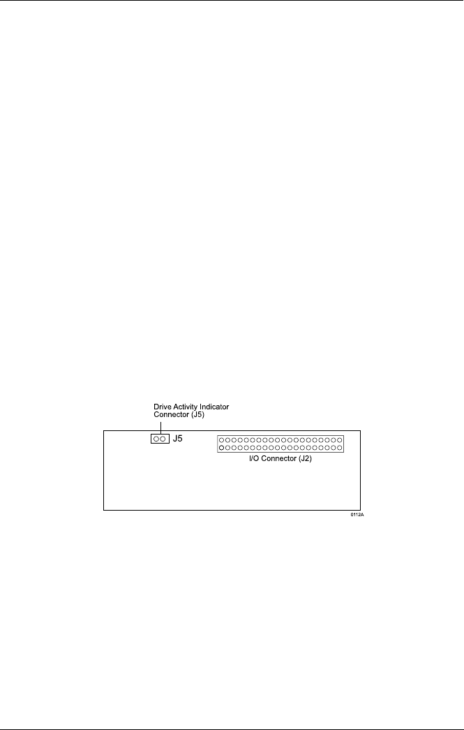
Figure 6: Drive Carrier Circuit Board
INSTALLATION
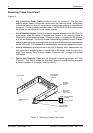
InstallingtheDriveintotheCarrier
NOTE: A #2 Phillips screwdriver will be required during this procedure.
While performing the steps in this section, work on a soft surface to prevent excessive shock
to the drive being installed. Also refer to the manufacturer's documentation provided with the
drive.
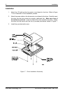
1. Remove the drive from its protective packaging.
2. Plastic Drive Bezel: If the drive came equipped with a plastic front bezel, it must
be removed before installing the drive into the drive carrier.
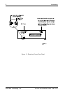
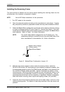
3. Master/Slave Drive Selection: In most cases, the drive will be factory-configured
as a Master Ultra ATA133 drive using a jumper plug on the drive itself. No con-
figuration changes are required. For multiple drive configurations, it is necessary
to set the first Ultra ATA133 drive as Master and the second Ultra ATA133 drive to
Slave. This can be done by changing the jumper on the Ultra ATA133 drive itself
(refer to your drive manufacturer documentation for further information).
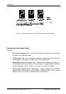
Drive Activity Indicator Connector J5 (Drive Carrier Circuit Board)
Jumper removed (factory default) disables drive activity indicator (Figure 4).
Jumper installed enables drive activity indicator.
NOTE: If two (2) drives are installed (with J5 enabled on both drives), both drive activity
indicators will flash simultaneously, even if only one drive is being accessed.