


DE100i-A100 User's Guide - Rev. C02 StorCase Technology, Inc.
Installation 13
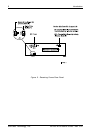
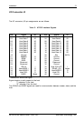
Table 2: AT/IDE Interface Signals
The I/O connector (J2) pin assignments are as follows:
I/O Connector J2
Pin Signal I/O Pin Signal I/O
01 Host Reset- O 02 Ground
03 Host Data 7 I/O 04 Host Data 8 I/O
05 Host Data 6 I/O 06 Host Data 9 I/O
07 Host Data 5 I/O 08 Host Data 10 I/O
09 Host Data 4 I/O 10 Host Data 11 I/O
11 Host Data 3 I/O 12 Host Data 12 I/O
13 Host Data 2 I/O 14 Host Data 13 I/O
15 Host Data 1 I/O 16 Host Data 14 I/O
17 Host Data 0 I/O 18 Host Data 15 I/O
19 Ground 20 Key No Pin
21 DMARQ O 22 Ground
23 DIOW- O 24 Ground
25 DIOR- O 26 Ground
27 Reserved 28 Reserved
29 Reserved 30 Ground
31 IRQ 14 I 32 Host IO16-(AT) I
33 Host ADDR 1 O 34 PDIAG- (16) Notes
35 Host ADDR 0 O 36 Host ADDR 2 O
37 Host CS0- O 38 Host CS1- O
39 DASP- Notes 40 Ground
- Indicates an active-low signal.
Signal direction is with respect to the host.
"I" indicates To the host
"O" indicates From the host
The /PDIAG and /DASP signals are used for communication between master, slave, and the
host.