


14 Sun Enterprise 4000 System Centerplane Upgrade Guide • January 1999
4. With a wrist strap attached, gently pull the TOD/NVRAM chip from the clock
board.
5. Align the TOD/NVRAM chip removed from the original clock board with the
connector on the upgrade clock board so that pin 1 on the chip is aligned with pin
1 on the board.
■ A small crescent-shape indentation on both the chip and the connector denotes
the top (mate these areas).
■ A small round indentation on the corner of the chip denotes pin 1.
6. Ensure that all pins on the TOD/NVRAM chip are aligned correctly with the
board connector pins.
Caution – To avoid system damage, make sure that you connect pin 1 on the TOD
chip into pin 1 on the board connector.
7. Gently press on the top of the chip to seat it.
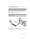
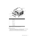
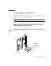
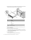
8. Carefully insert the board in the clock board slot component-side up, ensuring
that the board does not slip out of the card guides.
9. Use the open extraction levers to seat the board. Push the board into the card cage,
then simultaneously press both extraction levers to seat the board on the
centerplane.
Do not press on the board front panel to seat it, doing so will damage the connector
pins.
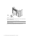
10. Secure the board to the chassis using the two captive screws, one on each side.
11. Connect any applicable interface cables to the front panel of the board.
This concludes the hardware portion of the clock board upgrade. Continue with the
next section, “Updating the System Flash PROM” to complete the procedure.
Updating the System Flash PROM
After replacing the clock board, update the system flash PROM. If you have internet
access, the patch can be downloaded using the following procedure. If you do not
have internet access, obtain the PROM patch software from your local Sun service
provider.
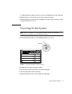
After the system flash PROM is reprogrammed, the flash utility attempts to reboot
the system. If the system fails to auto reboot, power cycle or reset the system by
pressing the reset button.
!