


v
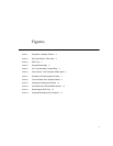
Figures
FIGURE 1 Keyswitch in Standby Position 2
FIGURE 2 AC Power Switch—Rear View 2
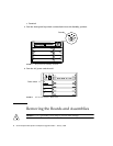
FIGURE 3 SCSI Tray 3
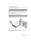
FIGURE 4 Keyswitch Assembly 4
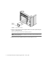
FIGURE 5 Fan Tray Assembly—System Rear 5
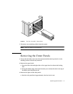
FIGURE 6 Outer Panels—Sun Enterprise 4000 System 7
FIGURE 7 Orientation of Empty System Chassis 8
FIGURE 8 Front and Rear of the System Chassis 9
FIGURE 9 Centerplane Replacement Detail 10
FIGURE 10 Clock Board and TOD/NVRAM Location 13
FIGURE 11 Removing the SCSI Tray 16
FIGURE 12 Keyswitch Standby and On Positions 17