2-2 Ultra Enterprise 6000/5000/4000 Systems Installation Guide—November 1996
2
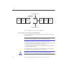
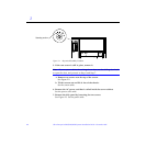
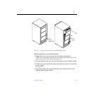
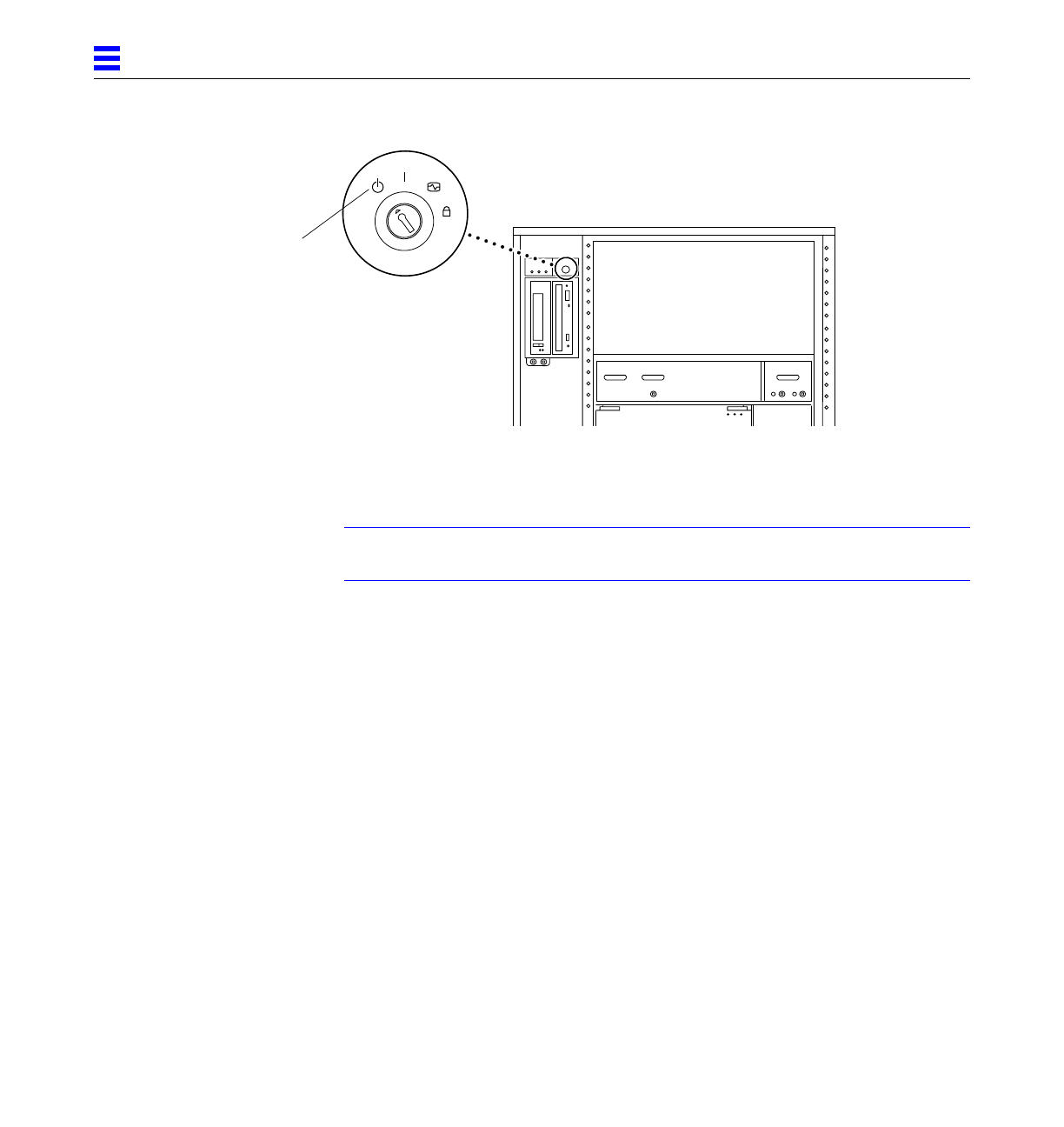
Figure 2-1 Keyswitch Standby Position
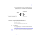
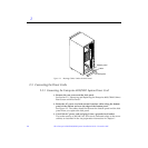
5. If the rear screen is still in place, remove it.
Note – If your system cabinet has a hinged rear door, use the sliding door latch
to open the door, and proceed to Step 6 and Step 7.
a. Remove two screws near the top of the screen.
See Figure 2-2.
b. Tilt the screen out and lift it free of the chassis.
Set the screen aside.
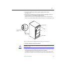
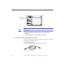
6. Remove the AC power cord that is coiled inside the server cabinet.
Set the power cord aside.
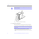
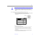
7. Remove the kick panel by loosening the two screws.
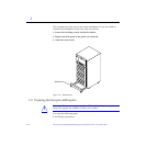
See Figure 2-3. Set the panel aside.
Standby position


