


Chapter 6 Configuring VLANs 29
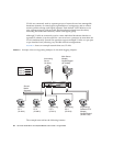
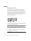
The physical LAN network consists of a switch, two servers, and five clients. The
LAN is logically organized into three different VLANs, each representing a different
IP subnet.
■ VLAN 1 is an IP subnet consisting of the Main Server, Client 3, and Client 5. This
represents an engineering group.
■ VLAN 2 includes the Main Server, Clients 1 and 2 by means of a shared media
segment, and Client 5. This is a software development group.
■ VLAN 3 includes the Main Server, the Accounting Server, and Client 4. This is an
accounting group.
The Main Server is a high-use server that needs to be accessed from all VLANs and
IP subnets. The server has a Sun 10GbE XFP SR PCI Express Card installed. All three
IP subnets are accessed by means of the single physical Ethernet adapter interface.
The server is attached to one of the switch’s Gigabit Ethernet ports, which is
configured for VLANs 1, 2, and 3. Both the Ethernet adapter and the connected
switch port have tagging turned on. Because of the tagging VLAN capabilities of
both devices, the server is able to communicate on all three IP subnets in this
network, but continues to maintain broadcast separation between all of those
subnets. The following list describes the components of this network:
■ The Accounting Server is available to only VLAN 3. The Accounting Server is
isolated from all traffic on VLANs 1 and 2. The switch port connected to the
server has tagging turned off.
■ Clients 1 and 2 are attached to a shared media hub that is then connected to the
switch. Clients 1 and 2 belong only to VLAN 2. Those clients are logically in the
same IP subnet as the Main Server and Client 5. The switch port connected to this
segment has tagging turned off.
■ Client 3 is a member of VLAN 1. This client can communicate only with the Main
Server and Client 5. Tagging is not enabled on Client 3’s switch port.
■ Client 4 is a member of VLAN 3. This client can communicate only with the
servers. Tagging is not enabled on Client 4’s switch port.
■ Client 5 is a member of both VLANs 1 and 2. This client has a Sun 10GbE XFP SR
PCI Express Card installed. Client 5 is connected to switch port 10. Both the
Ethernet adapter and the switch port are configured for VLANs 1 and 2, and both
have tagging enabled.
VLAN tagging is only required to be enabled on switch ports that create trunk links
to other VLAN-aware Ethernet switches, or on ports connected to tag-capable end-
stations, such as servers or workstations with VLAN-aware Ethernet adapters.