


Chapter 3: System Interface
3-1
Chapter 3
System Interface
3-1 Overview
There are several LEDs on the two control panels as well as others on the SATA
drive carriers to keep you constantly informed of the overall status of the system as
well as the activity and health of specifi c components. There are also two buttons
on each control panel. This chapter explains the meanings of all LED indicators
and the appropriate response you may need to take. Note that the server has two
control panels, one for each serverboard installed in the system. This allows each
serverboard to be controlled independently of the other.
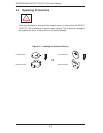
3-2 Control Panel Buttons
There are two push-buttons located on each control panel: a reset button and a
power on/off button.
Reset
Depressing the reset button will reboot only the serverboard it is associated with.
Power
This is the main power button, which is used to apply or turn off the main system
power only to the serverboard it is connected to. Depressing this button removes
the main power but keeps standby power supplied to the serverboard.