


5-12
SUPERSERVER 6015TC-T/6015TC-10G User's Manual
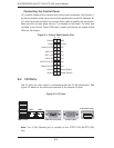
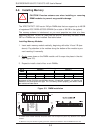
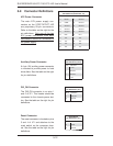
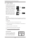
Reset Connector
The reset connector is located on pins
3 and 4 of JF1 and attaches to the
reset switch on the computer chas-
sis. See the table on the right for pin
defi nitions.
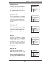
PW_ON Connector
The PW_ON connector is on pins 1
and 2 of JF1. This header should be
connected to the chassis power but-
ton. See the table on the right for pin
defi nitions.
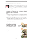
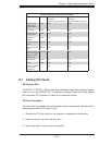
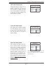
5-9 Connector Defi nitions
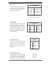
ATX Power Connector
The main ATX power supply con-
nectors on the X7DCT/X7DCT-10G
are proprietary 20-pin connections.
Refer to the table on the right for the
pin defi nitions. Only one of the two
ATX power connectors from each
serverboard should be connected to
the power supply
.
Reset Button
Pin Defi nitions (JF1)
Pin# Defi nition
3 Reset
4 Ground
Power Button
Pin Defi nitions (JF1)
Pin# Defi nition
1 PW_ON
2 Ground
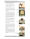
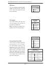
Auxiliary Power Connector
A 4-pin 12V auxiliary power connector
is included to provide power to hard
drive disks. See the table on the right
for pin defi nitions.
Auxiliary Power
Pin Defi nitions (JP10)
Pin# Defi nition
1 +12V
2 Ground
3 Ground
4 +5V
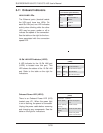
ATX Power 20-pin Connector
Pin Defi nitions (ATX Power 1/2)
Pin# Defi nition Pin # Defi nition
11 PS On 1 Ground
12 5VSB 2 Ground
13 Ground 3 Ground
14 Ground 4 Ground
15 Ground 5 Ground
16 NC2 6 NC1
17 12V 7 12V
18 12V 8 12V
19 12V 9 12V
20 12V 10 12V