


5-4
SUPERSERVER 6015TC-T/6015TC-10G User's Manual
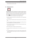
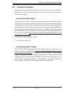
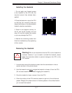
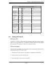
5-4 I/O Ports
The I/O ports are color coded in conformance with the PC 99 specifi cation. See
Figure 5-2 below for the colors and locations of the various I/O ports.
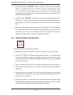
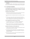
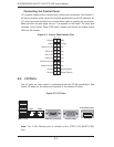
Figure 5-1. Control Panel Header Pins
Note: The 10 Gb Ethernet port is included on the X7DCT-10G (6015TC-10G)
only.
COM2 Port (Turquoise) VGA Port (Blue)USB 0/1 Ports
Figure 5-2. I/O Ports
NMI
x (Key)
Vcc
Vcc
Vcc
Vcc
Vcc
Vcc
Reset (Button)
Power (Button)
Ground
x (Key)
Power On LED
HDD LED
NIC1 LED
NIC2 LED
OH/Fan Fail LED
Power Fail LED
Ground
Ground
2 1
20 19
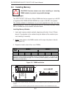
Connecting the Control Panel
JF1 contains header pins for various front control panel connectors. See Figure 5-1
for the pin locations of the various front control panel buttons and LED indicators. All
JF1 wires have been bundled into a single ribbon cable to simplify this connection.
Make sure the red wire plugs into pin 1 as marked on the board. The other end
connects to the Control Panel PCB board, located just behind the system status
LEDs on the chassis.
10 Gb Ethernet Port
LAN1 LAN2