


6-2
SUPERSERVER 6026TT-GTRF/GIBXRF/GIBQRF User's Manual
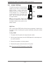
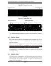
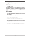
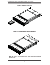
Figure 6-2. Chassis Rear View
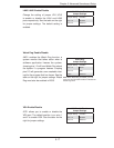
6-2 Control Panel
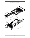
Each control panel on the front of the chassis must be connected to the JF2 con-
nector on its associated serverboard to provide you with system control buttons
and status indicators.
These wires have been bundled together in a ribbon cable to simplify the connection.
Connect the cable from JF2 on the serverboard to the control panel PCB (printed
circuit board). Make sure the red wire plugs into pin 1 on both connectors. Pull all
excess cabling out of the airfl ow path. The LEDs inform you of system status for
the serverboard it is connected to. See Chapter 3 for details on the LEDs and the
control panel buttons.
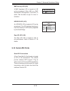
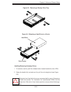
6-3 System Fans
The system has four hot-swappable 8-cm PWM fans to provide the cooling for both
nodes. The fans connect directly to the backplane but receive their power from the
serverboard they are connected to logically. Fan speed may be controlled by a
setting in BIOS (see Chapter 7).
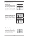
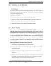
Figure 6-1. Chassis Front View
USB Ports COM Port VGA Port
LAN Ports
Dedicated IPMI LAN Port
Power Supply
PCI-Express x16 Card (1)PCI-Express x16 Card (1)
SATA Drives
Infi niBand Port*
USB Ports COM Port VGA Port
Infi niBand Port*
Dedicated IPMI LAN Port
Node A Control Panel Node B Control Panel
LAN Ports
*The Infi niBand ports are included on the 6026TT-GIBXRF and 6026TT-GIBQRF
only.