


Chapter 5: Advanced Serverboard Setup
5-7
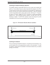
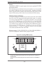
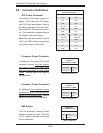
5-4 I/O Ports
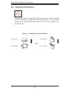
The I/O ports are color coded in conformance with the PC 99 specifi cation. See
Figure 5-2 below for the colors and locations of the various I/O ports.
Figure 5-2. Rear Panel I/O Ports
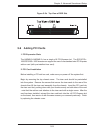
5-5 Installing Memory
Note: Check the Supermicro web site for recommended memory modules.
CAUTION
Exercise extreme care when installing or removing DIMM modules
to prevent any possible damage.
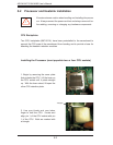
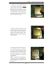
1. Insert each memory module vertically into its slot, paying attention to the notch
along the bottom of the module to prevent inserting the module incorrectly (see
Figure 5-3). See support information below.
2. Gently press down on the memory module until it snaps into place.
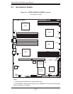
Note: Each processor has its own built-in memory controller, consequently each
CPU has a four-slot memory bank associated with it. (Memory installed into a bank
with no CPU present cannot be accessed.) 128 MB, 256 MB, 512 MB, 1 GB and 2
GB memory modules are supported. It is highly recommended that you remove the
power cord from the system before installing or changing any memory modules.