


5-12
AS1041M-T2/1041M-82 User's Manual
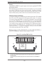
5-8 Connector Defi nitions
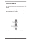
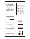
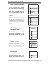
ATX Power Connector
The primary ATX power supply con-
nector (J1B1) meets the SSI (Super-
set ATX) 24-pin specifi cation. Refer to
the table on the right for the pin defi ni-
tions of the ATX 24-pin power connec-
tor. This connection supplies power to
the chipset, fans and memory.
Note: You must also connect the 8-pin
JPW1 and JPW2 power connectors to
your power supply (see below).
Required Connection
ATX Power 24-pin Connector
Pin Defi nitions (J1B1)
Pin# Defi nition Pin # Defi nition
13 +3.3V 1 +3.3V
14 -12V 2 +3.3V
15 COM 3 COM
16 PS_ON 4 +5V
17 COM 5 COM
18 COM 6 +5V
19 COM 7 COM
20 Res (NC) 8 PWR_OK
21 +5V 9 5VSB
22 +5V 10 +12V
23 +5V 11 +12V
24 COM 12 +3.3V
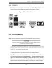
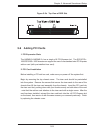
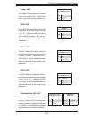
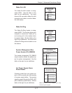
Processor Power Connector
In addition to the primary ATX power
connector (above), the 8-pin proces-
sor power connector at JPW1 must
also be connected to your power
supply. See the table on the right for
pin defi nitions.
Processor Power
Connector 1
Pin Defi nitions (JPW1)
Pins Defi nition
1 through 4 Ground
5 through 8 +12V
Required Connection
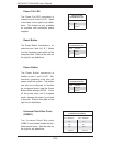
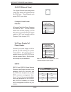
Processor Power Connector
An additional 8-pin processor power
connector at JPW2 must also be con-
nected to your power supply. See the
table on the right for pin defi nitions.
Processor Power
Connector 2
Pin Defi nitions (JPW2)
Pins Defi nition
1 through 4 Ground
5 through 8 +12V
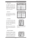
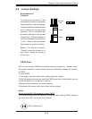
NMI Button
The non-maskable interrupt button
header is located on pins 19 and 20
of JF1. Refer to the table on the right
for pin defi nitions.
NMI Button
Pin Defi nitions (JF1)
Pin# Defi nition
19 Control
20 Ground
NMI not supported