


Chapter 5: Advanced Serverboard Setup
5-15
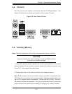
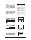
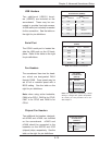
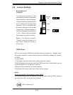
Fan Headers
The serverboard has nine fan head-
ers, which are designated FAN1
through FAN9. Fans speed may be
set to full or variable speed with a
BIOS setting. See the table on the
right for pin defi nitions.
Note: when using active heatsinks,
FAN4 is for CPU1, FAN3 is for CPU2,
FAN7 is for CPU3 and FAN8 is for
CPU4.
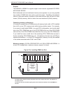
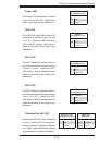
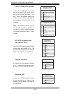
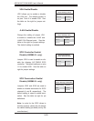
Serial Port
The COM1 serial port is located be-
side the USB ports on the I/O back-
plane. Refer to the table on the right
for pin defi nitions.
Note: NC indicates no connection.
Serial Port Pin Defi nitions
(COM1)
Pin # Defi nition Pin # Defi nition
1 DCD 6 DSR
2 RXD 7 RTS
3 TXD 8 CTS
4 DTR 9 RI
5 Ground 10 NC
Fan Header
Pin Defi nitions
(FAN1-9)
Pin# Defi nition
1 Ground (Black)
2 +12V/9V (Red)
3 Tachometer
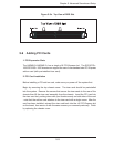
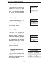
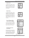
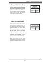
USB Headers
Two additional USB2.0 head-
ers (USB2/3) are included on the
serverboard. These may be con-
nected to provide front side access.
A USB cable (not included) is needed
for the connection. See the table on
the right for pin defi nitions.
Universal Serial Bus Headers
Pin Defi nitions (USB2/3)
USB2
Pin # Defi nition
USB3
Pin # Defi nition
1 +5V 1 +5V
2 PO- 2 PO-
3 PO+ 3 PO+
4 Ground 4 Ground
5 Key 5 No connection
Note: Fan speed may controlled by a BIOS
setting to change with system temperature.
As a result, pin 2 may be either 12V or 9 V.
See Chapter 4.
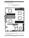
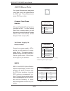
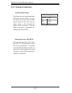
Chipset Fan Headers
Two additional fan headers, designat-
ed nFAN3 and nFAN4, are included
on the serverboard. nFAN3 and
nFAN4 should be connected to the
heatsinks on the MCP55 and 8132
(chipset) chips, respectively. See the
table on the right for pin defi nitions.
Chipset Fan Headers
Pin Defi nitions
(nFAN3-4)
Pin# Defi nition
112V
2 Ground