


Chapter 2: Installation
2-11
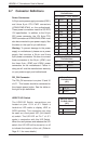
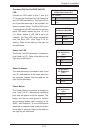
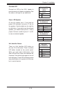
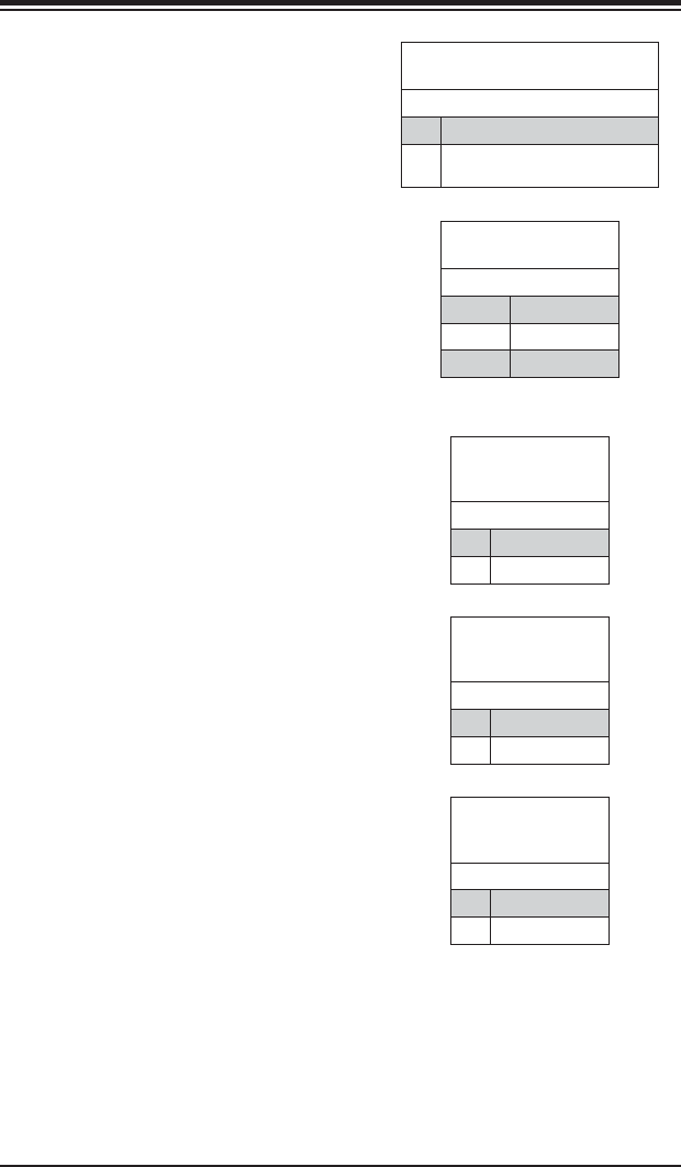
Reset Connector
The reset connector is located on pins 3 and
4 of JF1 and attaches to the reset switch on
the computer chassis. See the table on the
right for pin defi nitions.
Reset Button
Pin Defi nitions
(JF1)
Pin# Defi nition
3 Reset
4 Ground
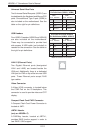
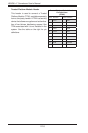
Overheat (OH)/Fan Fail/PWR Fail/UID
LED
Connect an LED cable to pins 7 and 8 of
JF1 to use the Overheat/Fan Fail/Power Fail
and UID LED connections. The Red LED on
pin 8 provides warnings of an overheat, fan
failure or power failure. The Blue LED on pin
7 works as the UID LED indicator for the front
panel UID switch located on pins 13~14 of
JF1. When Jumper J_UID_OW is set to off
(default), the Red LED takes precedence
over the Blue LED. (See Page 2-19 for
details.) Refer to the table on the right for
pin defi nitions.
OH/Fan Fail/ PWR Fail/Blue_UID
LEDPin Defi nitions (JF1)
Pin# Defi nition
7 Blue_LED-Cathode(UID)/5.5V.SB
8 OH/Fan Fail/PWR Fail/UID LED
(Red)
OH/Fan Fail/PWR Fail
LED Status (Red LED)
State Indication
Off Normal
On Overheat
Flashing Fan Fail
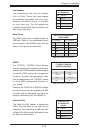
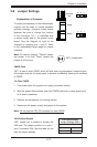
Power Fail LED
The Power Fail LED connection is located on
pins 5 and 6 of JF1. Refer to the table on the
right for pin defi nitions.
PWR Fail LED
Pin Defi nitions
(JF1)
Pin# Defi nition
5 3.3V
6 PWR Fail LED
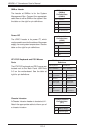
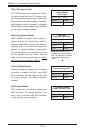
Power Button
The Power Button connection is located on
pins 1 and 2 of JF1. Momentarily contacting
both pins will power on/off the system. This
button can also be confi gured to function
as a suspend button (with a setting in the
BIOS - see Chapter 4). To turn off the power
when set to suspend mode, press the button
for at least 4 seconds. Refer to the table on
the right for pin defi nitions.
Power Button
Pin Defi nitions
(JF1)
Pin# Defi nition
1 PWR
2 Ground