


Chapter 2: Installation
2-15
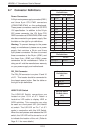
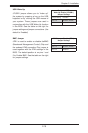
Power LED/Speaker
On the JD1 header, pins 1~3 are used for
power LED indication, and pins 4-7 are for
the speaker. See the tables on the right for
pin defi nitions. If you wish to use the onboard
speaker, you should close pins 6~7 with a
jumper. Connect a cable to pins 4~7 of JD1
to use an external speaker.
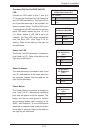
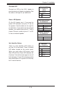
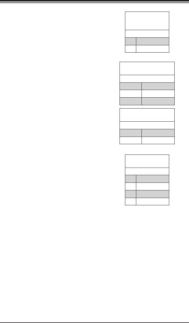
Speaker Connector
Pin Defi nitions
Pin Setting Defi nition
Pins 4~7 External Speaker
Pins 6~7 Internal Speaker
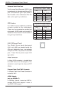
PWR LED Connector
Pin Defi nitions
Pin Setting Defi nition
Pin 1 Anode (+)
Pin2 Cathode (-)
Pin3 NA
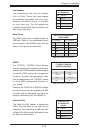
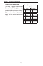
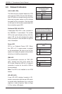
Overheat LED
Connect an LED to the JOH1 header to
provide warning of chassis overheating. See
the table on the right for pin defi nitions.
Overheat LED
Pin Defi nitions
(JOH1)
Pin# Defi nition
1 3.3V
2 OH Active
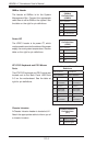
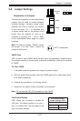
UID Button
Pin Defi nitions
Pin# Defi nition
1 Ground
2 Ground
3 Button In
4 Ground
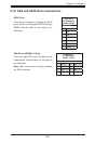
Unit Identifi er Button
There is a Unit Identifi er (UID) button on
the rear I/O of the board. There is another
UID button located on the control panel.
When you push either UID button, both
Rear UID and Front Panel UID Indicators will
illuminate. Push either button again to turn off
both indicators. These UID indicators provide
easy identifi cation of a system unit that may
be in need of service.