


5-17
Chapter 5: Chassis Setup and Maintenance
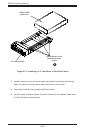
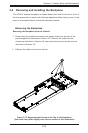
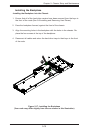
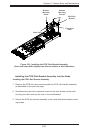
Installing the Motherboard
1. Review the documentation that came with your motherboard. Become familiar
with component placement, requirements, cautions, and cable connections.
2. Remove the node from the chassis as described in Section 5-2, remove the
node from the chassis as described in Section 5-4 and remove the cover from
the node as described in Section 5-5.
3. Compare the holes in the motherboard to those in the node. Add or remove
standoffs as necessary.
4. Lay the motherboard in the node, aligning the standoffs with the motherboard.
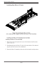
5. Secure the motherboard to the oor of the node tray using the rounded, Phil-
lips head screws included for this purpose. Do not exceed eight pounds of
torque when tightening down the motherboard.
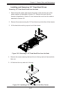
6. Install the expansion card associated with the motherboard if the chassis is a
hot-swappable version. Refer to the next section for instructions on installing
the expansion card
7. Secure the CPU(s), heatsinks, and other components to the motherboard as
described in the motherboard documentation. Do not exceed eight pounds of
torque when tightening down the motherboard.
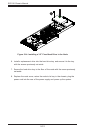
8. Connect the cables between the motherboard, backplane, chassis, front
panel, and power supply, as needed. The fans may be temporarily removed
to allow access to the backplane ports.
9. Replace the expansion card bracket and secure the bracket with a screw.
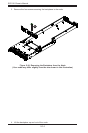
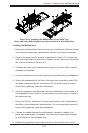
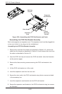
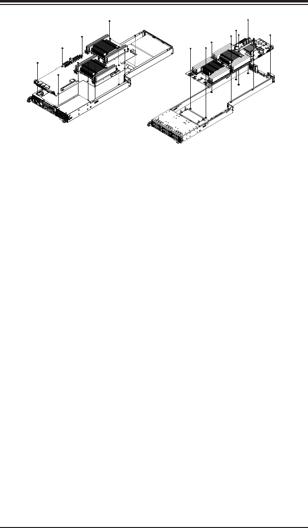
Figure 5-18: Installing the Motherboard in the Node Tray
(Your node may differ slightly from the one shown in this illustration)