


5-29
Chapter 5: Chassis Setup and Maintenance
The SCF418 chassis includes redundant 1620W power supplies. These power sup-
plies are auto-switching capable. This enables the power supplies to automatically
sense and operate at a 100v to 240v input voltage. An amber light will be illuminated
on the power supply when the power is off. An illuminated green light indicates that
the power supply is operating.
Power Supply Replacement
The SCF418 chassis utilizes redundant power supplies. In the unlikely event that
the power supply unit needs to be replaced, one power supply can be removed,
without powering down the system. Replacement units can be ordered directly from
Supermicro (See the contact information in the Preface of this manual).
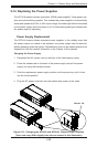
Changing the Power Supply
1. Disconnect the AC power cord on the back of the failed power supply.
2. Press the release tab on the back of the power supply and pull the power
supply out using the handle provided.
3. Push the replacement power supply module into the power bay until it clicks
into the locked position.
4. Plug the AC power cord back into the module and power up the node.
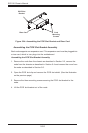
5-14 Replacing the Power Supplies
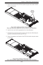
Release Tab
Figure 5-31: Changing the SCF418 and SCF418L Chassis Power Supplies
(Your node may differ slightly from the one shown in this illustration)