


Chapter 1: Introduction
1-5
Introduction
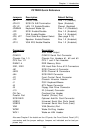
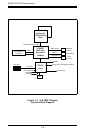
P3TDDR Quick Reference
Jumpers Description Default Setting
JBT1 CMOS Clear Pins 1-2 (Normal)
JPA1/2 SCSI Ch A/B Termination Open (Enabled)
JPL1/2 LAN 1/2 Enable/Disable Closed (Enabled)
JPWAKE Keyboard Wake-Up Pins 1-2 (Disabled)
JP2 SCSI Enable/Disable Pins 1-2 (Enabled)
JP3 VGA Enable/Disable Pins 1-2 (Enabled)
JP6, JP7 Front Side Bus Speed Select (See page 2-12)
JP8 Speaker Enable/Disable Pins 1-2 (Enabled)
JP10 VGA IRQ Enable/Disable Pins 1-2 (Enabled)
Connectors Description
AGP AGP Video Output
COM1/2 COM1/2 Serial Port Connector
Chassis Fan 1-3 Chassis Fan Headers #1, #2 and #3
CPU Fan 1/2 CPU 1 and 2 Fan Headers
DIMM 1-4 DDR Memory Slots
IDE1, IDE2 IDE Hard Disk Drive #1/2 Connectors
JA1 SCSI Channel A Connector
JA2/3 SCSI Channel B Connectors
JA4 SCSI RAID Connector
JF1 Front Control Panel Connector
JL1 Chassis Intrusion Header
J1 PS/2 Keyboard/Mouse
J6 ATX Power Connector
J9 Floppy Disk Drive Connector
J10 IR (Infrared) Connector
OH Fan Overheat Fan Header
Parallel Port Parallel (Printer) Port
SCSI RAID Optional Add-On Card Connector
USB0/1 Universal Serial Bus Ports (back)
USB2/3 Universal Serial Bus Ports (front)
VGA VGA (Monitor) Port
WOM1 Wake-On-Ring Header
WOL1 Wake-on-LAN Header
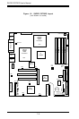
Also see Chapter 2 for details on the I/O ports, the Front Control Panel (JF1)
connectors and the jumper settings. Jumpers not indicated are for test pur-
poses only.