


2-8
SUPER P3TDDR User’s Manual
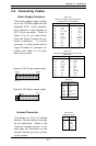
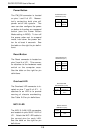
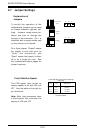
Reset Button
The Reset connector is located on
pins 3 and 4 of JF1. This connec-
tor attaches to the hardware reset
switch on the computer case.
See the table on the right for pin
definitions.
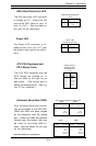
Power Button
The PW_ON connector is located
on pins 1 and 2 of JF1. Momen-
tarily contacting both pins will
power on/off the system. The
user can also configure the power
on button to function as a suspend
button (see the Power Button
Mode setting in BIOS). To turn off
the power when set to suspend
mode, hold down the power but-
ton for at least 4 seconds. See
the table on the right for pin defini-
tions.
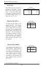
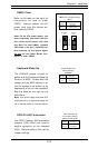
NIC1/2 LED
The NIC1/2 (LAN) LED connectors
are located on pins 9&10/11&12 of
JF1. Attach the NIC LED cable to
the correct pins for each LAN.
See the table on the right for pin
definitions.
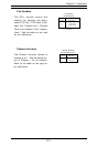
Overheat LED
The Overheat LED connector is lo-
cated on pins 7 and 8 of JF1. It
attaches to an LED to to provide
warning of chassis overheating.
See Table 2-6 for pin definitions.
Pin
Number
1
2
Definition
PW_ON
Ground
Power Button Pin
Definitions (JF1)
Pin
Number
3
4
Definition
Ground
Reset
Reset Button Pin
Definitions (JF1)
Pin
Number
7
8
Definition
LED +
LED -
Overheat LED
Pin Definitions (JF1)
Pin
Number
9/11
10/12
Definition
LED +
NIC1/2 LED Pin
Definitions (JF1)
LED -