


Chapter 2: Installation
2-9
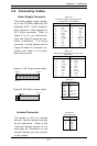
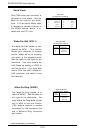
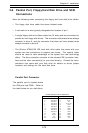
Power LED
The Power LED connector is lo-
cated on pins 15 to 16 of JF1. See
the table on the right for pin defini-
tions.
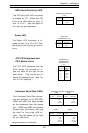
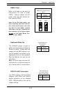
HDD (Hard Disk Drive) LED
The IDE hard drive LED connector
is located on JF1. Attach the IDE
hard drive LED cable to pins 13
and 14 of JF1. See the table on
the right for pin definitions.
Pin
Number
Definition
LED +
LED -
HDD LED Pin Definitions
(JF1)
13
14
Pin
Number
Definition
LED +
LED -
Power LED
Pin Definitions (JF1)
15
16
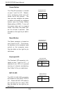
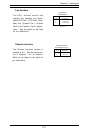
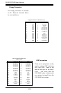
ATX PS/2 Keyboard and
PS/2 Mouse Ports
The ATX PS/2 keyboard and the
PS/2 mouse are located on J1.
See the table on the right for pin
definitions. (The mouse port is
above the keyboard port. See Fig-
ure 2-3 for locations.)
PS/2 Keyboard
and Mouse Port
Pin Definitions
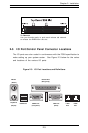
(J1)
Pin
Number
1
2
3
4
5
6
Definition
Data
NC
Ground
VCC
Clock
NC
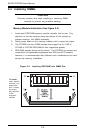
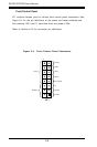
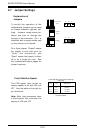
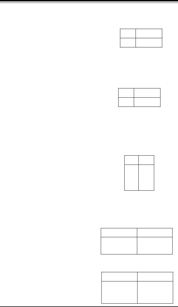
Universal Serial Bus (USB)
Four Universal Serial Bus connec-
tors are provided on the P3TDDR.
USB0 and USB1 are ports located
on the backplane near the mouse
port. USB2 and USB3 are headers
located near the battery that may
be used for front-side USB ac-
cess. See the tables on the right
for pin definitions.
Universal Serial Bus Pin Definitions
Pin
Number Definition
1+5V
2P0-
3P0+
4Ground
Pin
Number Definition
1+5V
2P0-
3P0+
4Ground
Pin
Number Definition
1+5V
2P0-
3P0+
4
Ground
5
Pin
Number Definition
1+5V
2P0-
3P0+
4 Ground
5 Ground
USB3USB2
USB1USB0
Ground
Note: NC indicates no connnection.