


2-10
SUPER PIIIDM6/PIIIDM4/PIIIDM3/PIIIDME User's Manual
Installation
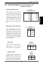
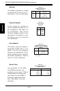
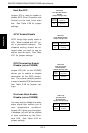
Table 2-15
Fan Header Pin Definitions
(THRM FAN, CPU1/2, CHASSIS
FAN1/2)
Pin
Number
1
2
3
Definition
Ground (black)
+12V (red)
Tachometer
* Caution: These fan headers
are DC power.
Fan Headers*
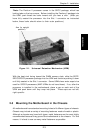
The thermal control fan header is
designated THRM FAN on your
board. The CPU and chassis fan
headers are designated CPU1,
CPU2, CHASSIS FAN1 and CHAS-
SIS FAN2, respectively. Refer to
Table 2-15 for pin definitions.
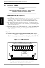
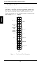
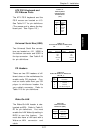
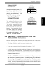
Serial Ports
Two connectors, for the COM1
and COM2 serial ports, are
provided on your board. COM1 is
located below the parallel port
(see Figure 2-3) and COM2 is
located just behind the Game
Port. See Table 2-16 for pin
definitions.
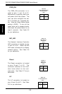
Table 2-16
Serial Port Pin Definitions
(COM1, COM2)
Pin Number Definition
1 DCD
2 DSR
3 Serial In
4 RTS
5 Serial Out
Pin Number Definition
6CTS
7 DTR
8RI
9 Ground
10 NC
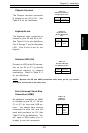
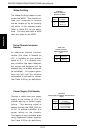
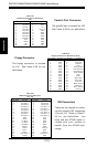
Speaker
The speaker connection is located
on pins 28, 30, 32 and 34 of JF1.
See Table 2-13 for pin definitions.
Table 2-13
Speaker Connector Pin
Definitions (JF1)
Pin
Number
28
30
32
34
Function
+
Key
Definition
Red wire, Speaker data
No connection
Key
Speaker data
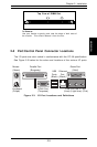
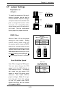
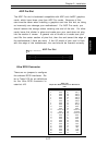
Infrared Header
A 6-pin header for infrared de-
vices is located just below JF1 on
the motherboard. See Table 2-14
for pin definitions. Also, see the
Technical Support section of our
web page for information on infra-
red devices you can connect to
the motherboard.
Pin
Number
1
2
3
4
5
Definition
+5V
Key
IRRX
Ground
IRTX
Table 2-14
Infrared (IR) Pin
Definitions