


Chapter 2: Installation
2-13
Installation
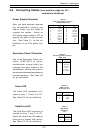
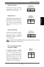
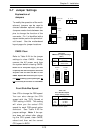
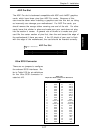
CMOS Clear
Refer to Table 2-24 for the jumper
settings to clear CMOS. Always
remove the AC power cord from
the system before clearing CMOS.
NOTE: For an ATX power supply, you must
completely shut down the system, remove the
AC power cord and
then
use JBT1 to clear
CMOS. Replace JBT1 back to the pin 1-2 posi-
tion before powering up the system again. Do
not use the PW_ON connector to clear CMOS.
Table 2-24
CMOS Clear Jumper Settings
(JBT1)
Jumper
Position
1-2
2-3
Definition
Normal
CMOS Clear
Position
1-2
Position
2-3
Normal
CMOS Clear
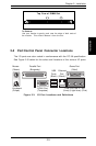
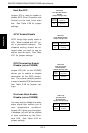
2-7 Jumper Settings
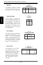
Explanation of
Jumpers
To modify the operation of the moth-
erboard, jumpers can be used to
choose between optional settings.
Jumpers create shorts between two
pins to change the function of the
connector. Pin 1 is identified with a
square solder pad on the printed cir-
cuit board. See the motherboard
layout pages for jumper locations.
Connector
Pins
Jumper
Cap
Setting
Pin 1-2 short
3 2 1
3 2 1
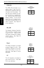
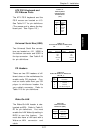
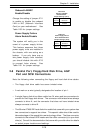
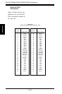
Front Side Bus Speed
Use JP3 to change the FSB speed.
You can also change the CPU
speed with the "CPU Speed at
FSB" setting in BIOS. This setting
will show you the actual CPU
speed for each FSB speed option
selected. See Table 2-25 for
jumper settings. Note: If the sys-
tem does not reboot after chang-
ing the CPU speed, clear CMOS,
reboot and then set the correct
CPU speed in BIOS.
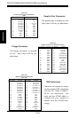
Table 2-25
Front Side Bus Speed
Jumper Settings (JP3)
Jumper
Position
1-2
2-3
OFF
Definition
Auto
133 MHz
100 MHz
* Note: The Auto setting allows
the CPU to set the speed.