


Chapter 2: Installation
2-15
Installation
2-8 Parallel Port, Floppy/Hard Disk Drive, AGP
Port and SCSI Connections
Note the following when connecting the floppy and hard disk drive cables:
• The floppy disk drive cable has seven twisted wires.
• A red mark on a wire typically designates the location of pin 1.
• A single floppy disk drive ribbon cable has 34 wires and two connectors to
provide for two floppy disk drives. The connector with twisted wires always
connects to drive A, and the connector that does not have twisted wires
always connects to drive B.
• The 80-wire ATA66 IDE hard disk drive cable that came with your system has
two connectors to support two drives. This special cable should be used to
take advantage of the speed this new technology offers. The blue connector
connects to the onboard IDE header and the other connector(s) to your hard
drive(s). Consult the documentation that came with your disk drive for details
on actual jumper locations and settings.
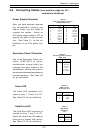
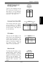
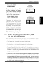
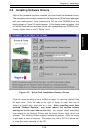
Onboard LAN/NIC
Enable/Disable
Change the setting of jumper JP11
to enable or disable the onboard
LAN or NIC (Network Interface
Card) on your motherboard. See
Table 2-30 for jumper settings.
Jumper
Position
Open
Closed
Definition
Disabled
Enabled
Table 2-30
Onboard LAN/NIC
Enable/Disable
Jumper Settings (JP11)
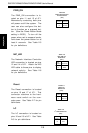
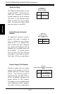
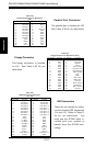
Power Supply Failure
Alarm Enable/Disable
The system will notify you in the
event of a power supply failure.
This feature assumes that three
power supply units are installed in
the chassis, with one acting as a
backup. If you only have one or
two power supply units installed,
you should disable this with JP13
to prevent false alarms. See
Table 2-31 for jumper settings.
Jumper
Position
Open
Closed
Definition
Disabled
Enabled
Table 2-31
Power Supply Failure
Alarm Enable/Disable
Jumper Settings (JP13)