


Chapter 2. Connecting
the Network Card to the
Data Network
12
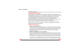
7. Switch on the computer and the switch.
If a protocol driver has not been loaded, go to Chapter 3. After driver installation, return to the
next step of this list.
If a protocol driver has been loaded, continue with the next step.
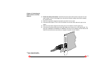
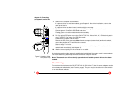
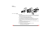
8. Check for correct polarity using the green Link LED (see Fig. 4) on the network card.
Constant green: connection established and active.
Flashing green: connection established and on standby.
9. For fiber optical SC Duplex connection (SK-NET GE-LX, -LX dual link, -SX, -SX dual link, patch
cord VF-45/SC): If the green Link LED fails to light:
Power off the computer and the switch.
Remove the SC duplex connector either from the computer (network card) or from the switch,
reverse the positions of TX and RX and re-connect.
Return to step 7 in this list.
If there is still no indication that a connection has been established you will need to check the
network card more closely (see Chapter 4).
10. Mark the correct polarity on the connector or the cable.
A physical connection to the network is established. Installation of the network card is now complete.
For future reference, please keep this manual with your computer manual.
Note: The network card will not be fully operational until suitable protocol drivers have been
loaded.
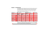
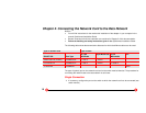
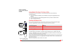
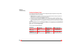
Dual Homing
For maximum fault tolerance the SK-NET GE-LX/-SX/-SX Volition/-T dual link server adapters can be
connected to two switch ports (see Features, page 6). The ports may be located on the same switch
or on two different switches.
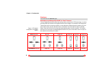
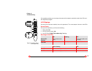
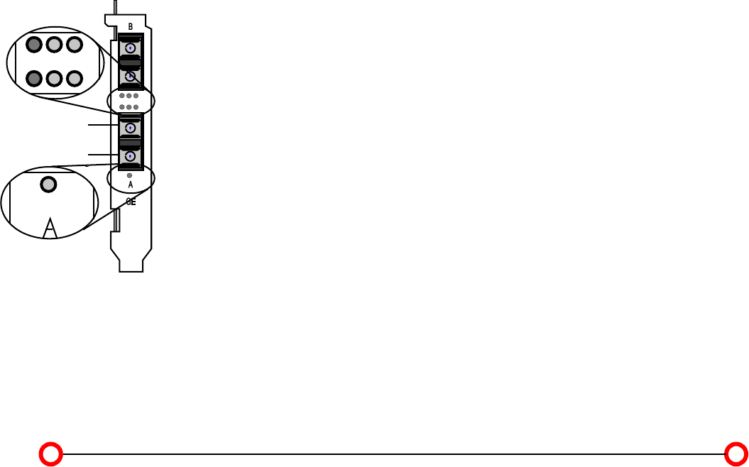
Link RX
TX
Status
RX
TX
Figure 3. Location of the
LEDs (dual link)