


TANDBERG 7000 MXP
230
All balanced inputs and outputs (A and B) use balanced line signals according to V.11 (RS422)
and single ended signals in accordance with V.10 (RS423).
For balanced signals a "0"=low voltage is defined as terminal A positive with respect to terminal
B.
For unbalanced signals a "0"= low voltage is defined as terminal positive with respect to GND.
Cable length max: 50 meter
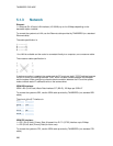
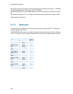
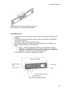
5.1.4 Data port
The data port(s) are implemented as Data Communications Equipment (DCE). The connector
used are female 9-pin D-subs.
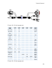
The TANDBERG main camera is normally connected to data port 2 and pin number 4 provides
12V DC / 1 Amps to the main camera. Otherwise the pin-outs for both data ports are the same.
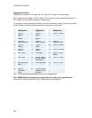
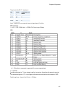
Signal name Direction Pin
number
Carrier detect, CD From
DCE
1
Receive data,
RXD
From
DCE
2
Transmit data,
TXD
To DCE 3
Data terminal
ready, DTR
From
DCE
4
Signal ground,
GND
5
Data set ready,
DSR
From
DCE
6
Ready to send,
RTS
To DCE 7
Clear to send,
CTS
From
DCE
8
Ring indicator, RI From
DCE
9