


Technical Description of TANDBERG Gateway with software version G2
D13192 Rev. 02 21
4.3 RS232 Interface/Application Programmable Interface (API)
Data Standards Data TANDBERG Dynamic Data Channel (DDC)
Modem Standard modem commands
Data Interfaces 1 x Data port, RS-232 (9-pin D-sub), Up to 115200 Baud for Data & Control
The RS232 port on the TANDBERG Gateway is implemented as Digital Circuit Terminating
Equipment (DCE).
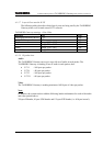
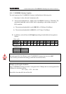
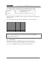
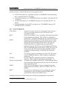
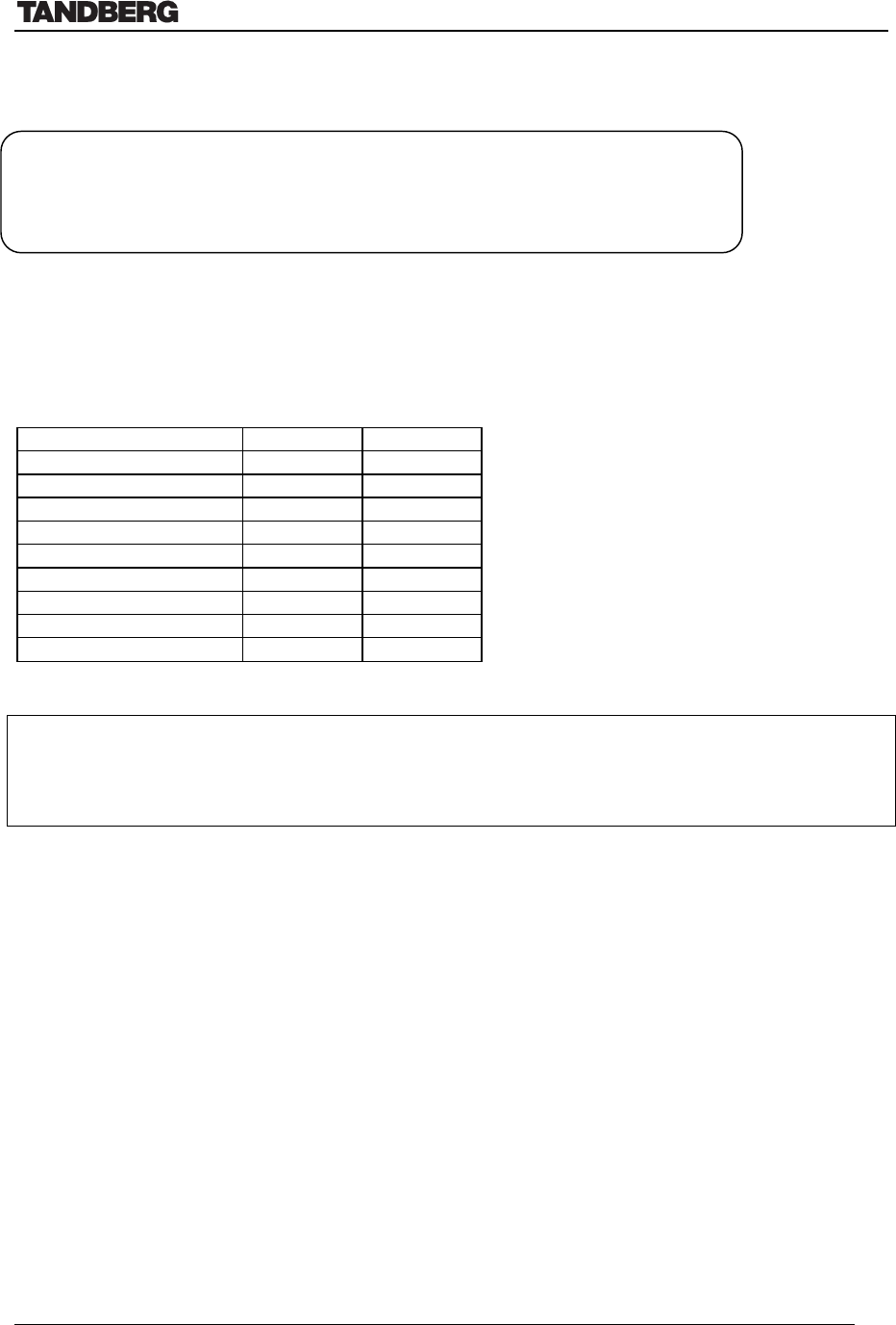
The connectors used are female 9-pin D-subs and the pin-out is shown in table below.
Signal Name Direction Pin number
Carrier detect, CD From DCE 1
Receive data, RXD From DCE 2
Transmit data, TXD To DCE 3
Data terminal ready, DTR From DCE 4
Signal ground, GND 5
Data set ready, DSR From DCE 6
Ready to send, RTS To DCE 7
Clear to send, CTS From DCE 8
Ring indicator, RI From DCE 9
Note: The API commands may also be accessed via Telnet, through the TANDBERG
Gateway’s Ethernet connection.
4.3.1 API commands
Please refer to the document ‘TANDBERG Gateway API’ (D13202) for details.
The RS232 port is used for local software upgrades, local control and diagnostics.
Also, refer to ‘TANDBERG SNMP’ (D12190) for SNMP implementation.