


PMP200XL Models
Owner’s Manual
• Avoid placing the inverter on or near heating vents, radiators or other
sources of heat. Do not place or use the inverter in direct sunlight. Ideal air
temperatures should be between 50°F and 80°F.
• In order to properly disperse the heat generated from the inverter while it is
operating, keep the inverter well ventilated. Keep the area surrounding the
inverter clear while in use.
• Do not use the inverter near flammable materials. Do not place the inverter in
areas such as battery compartments where fumes or gases may accumulate.
Inverter Protection Features
• Short Circuit Protection. The inverter will automatically shut down until
short is removed.
• Low Voltage Alarm. An alarm will sound when the voltage from the battery
discharges to 10.5 +/- 0.5 volts DC. This is an indication that the battery needs
to be recharged.
• Over Voltage Protection. The RED LED Indicator Light will illuminate and
the inverter will automatically turn itself off when the input exceeds 16.5 +/- 1
volt DC.
• Under Voltage Protection. The RED LED Indicator Light will illuminate and
the inverter will automatically turn itself off when the input is less than 10.0+/-
0.5 volts DC.
• Overload Protection. The RED LED Indicator Light will illuminate and
the inverter will automatically turn itself off when the continuous draw of
the equipment being operated exceeds 200 watts or the surge draw of the
equipment exceeds 400 watts.
• Thermal Protection. The RED LED Indicator Light will illuminate and the
inverter will automatically turn itself off when the circuit temperature exceeds
130°F.
Notes
• The inverter is equipped with a cooling fan, which is designed to run
continuously while the inverter is operating. Automatic shut down of the unit
caused by high circuit temperatures will occur when the cooling fan is unable
to maintain a cool enough temperature for safe operation.
• In the event of automatic shut down or a continuous audible alarm, turn the
inverter power switch to the OFF(O) position until the source of the problem
has been determined and resolved.
5
Television and Audio Suggestions
Although all COLEMAN® inverters are shielded and filtered to minimize
signal interference, some interference with your television picture may be
unavoidable, especially with weak signals. However, here are some suggestions
that may improve reception:
• Make sure the television antenna produces a clear signal under normal
operating conditions (at home plugged into a standard 110/120- volt AC
outlet). Also, ensure that the antenna cable is properly shielded and/or good
quality.
• Change the positions of the inverter, antenna cables and the television power
cord.
• Isolate the television, its power cord and antenna cables from the 12-volt
power source by running an extension cord from the inverter to the television
set.
• Coil the television power cord and the input cables running from the 12-volt
power source to the inverter.
• Attach an AC interference filter or similar product between the inverter and
the television power cord. These filters are available at most electronic supply
stores including Radio Shack.
Note
Inexpensive sound systems may emit a “buzzing” sound when operated with
an inverter. This is due to the inadequate filters in the sound system. There is
no solution to this problem other than purchasing a sound system with a higher
quality power supply.
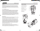
How Power Inverters Work
Power inverters convert low voltage DC (direct current) power to 110/120-volt
AC (alternating current) household power. This conversion process thereby
allows you to use household products, power tools, and other electronic
products away from normal AC power sources (standard 110/120V wall outlets).
Depending on the model and its rated capacity, inverters can draw power
either from standard 12-volt automobile and marine batteries or from portable
high power 12-volt power sources. The waveform that is generated by this
conversion is a “modified sine wave”. The modified sine wave produced by our
inverters has a root square mean (RMS) voltage of 110/120 volts, which is the
same as standard household power.
The majority of AC voltmeters are calibrated for RMS voltage under the
assumption that the measured waveform will be a pure sine wave. Therefore,
these meters will not read the RMS modified sine wave voltage correctly.
6
PMP200XL_122205M.indd 10-11 12/22/05 9:09:48 AM