Status and Events
4–2
Option 01 VXI Interface Module User Manual
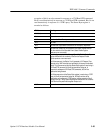
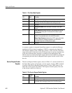
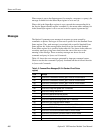
Table 4–1: The Status Byte Register
Bit
Decimal
Value
Function
0–1 – Not used.
2 4 Error/Event queue Not Empty indicates that information is
contained in the Error/Event queue and is waiting to be read.
3 – Not used.
4 16 Message Available shows that output is available in the Output
queue.
5 32 Event Status Bit indicates that one or more events have occurred
and the corresponding bits in the Standard Event Status register
have been set.
6 64 Request Service (obtained from a serial poll) shows that the
Option 01 has requested service from the GPIB controller.
Master Status Summary (obtained from *STB? query) summarizes
the Event Status bit, Message Available bits, and Error/Event
queue Not Empty bits in the Status Byte register.
7 – Not used.
A common example of using the Status Byte register is to enable the Message
Available bit. This is done by sending an *SRE 16 command to the Option 01
VXI Interface Module. If the *STB? query returns a value of 80, bit 4 (decimal
value of 16) and bit 6 (decimal value of 64) have been set (giving a decimal sum
of 80). Bit 4 indicates that a message is available in the output queue. Bit 6
indicates that a bit in the Status Byte register that has been enabled by setting the
corresponding bit in the Service Request Enable register (in this case bit 4) has
been set.
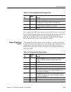
The Service Request Enable register, shown in Table 4–2, controls which bits in
the Status Byte register will generate a service request. Use the *SRE command
to set bits in the Service Request Enable register. Use the *SRE? query to see
which bits in this register are enabled. The response from this query is the sum
of the decimal values for all bits set.
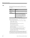
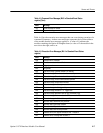
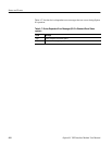
Table 4–2: The Service Request Enable Register
Bit
Decimal
Value
Function
0–1 – Not used
2 4 Error/Event queue Bit indicates that a service request will be
generated when a message is placed in the Error/Event queue.
Service Request Enable
Register


