


H
DMI Compliance & Sink Characterization Using DTG5000 Series Data Timing Generator
Application Note
3
www.tektronix.com/signal_sources
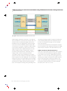
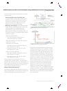
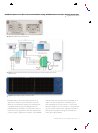
The basic TMDS transmission line is made up of three
data channels and a clock channel. Data consists of
8-bit pixels (256 discrete levels) in each of three
channels (R/G/B). These are encoded into ten-bits
words using 8B/10B encoding to minimize transitions
and to remove the DC component. The signals have
rise times on the order of 100 picoseconds. A pair of
TMDS lines is used when higher data rates are needed.
Figure 1 shows the flow of pixel data from the
graphics controller or Source device to the digital
Sink receiver.
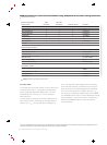
TMDS data rates range fr
om 22.5 megapixels per
second (Mpps) to 165 Mpps, equivalent to or up to
1.65 G bits per second at the maximum clock rate
of 165 MHz. The data rate depends on the display
resolution. The relationships of display resolution, bit
rate and clock frequency are shown in the Table 1.
Compliance Testing Tools and Solutions -
DTG5000 Series
The goal of compliance testing is to ensur
e interoper-
ability among the many hundreds of different HDMI
devices from as many manufacturers. By conforming
to published HDMI specifications, a device manufactur
er
can pave the way for a new product's acceptance in
the marketplace.
T
esting should also ensure that the designs are robust
enough to withstand the harsh treatment they can
expect to receive in the real world. As new displays
become more rugged, the devices that use them will
find their way into less sheltered environments than in
the past. Therefore, new devices should be tested to
comply with standards under a variety of operating
conditions, not just “nominal” or best-case conditions.
T
est parameters should r
each out beyond the basic
limits defined in the specifications.
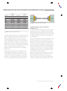
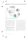
Figure 2 illustrates the major elements of the HDMI
transmission system: Source, Cable and Sink. The
Sour
ce signals ar
e tested at TP1 while the Sink
devices are tested at TP2. For testing cables, meas-
ur
ements must be performed at both TP1 and TP2.
Figure 2.
Test points for HDMI measurements.
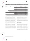
Display Clock
Standard Resolution Data Rate Frequency
VGA 640 x 480 252 Mb/s 25.2 MHz
SVGA 800 x 600 400 Mb/s 40 MHz
XGA 1024 x 768 650 Mb/s 65 MHz
SXGA 1280 x 1024 1080 Mb/s 108 MHz
UXGA 1600 x 1200 1620 Mb/s 162 MHz
640 x 480p 640 x 480 252 Mb/s 25.2 MHz
720 x 480p 720 x 480 270.27 Mb/s 27.027 MHz
576p 768 x 576 270 Mb/s 27 MHz
720p 1280 x 720 742.5 Mb/s 74.25 MHz
1
080i 1920 x 1080 742.5 Mb/s 74.25 MHz
Table 1.
Standards and respective data rates.